


Steve_switch
New Member
- Joined
- Jun 14, 2020
- Messages
- 13
My expensive ATS-EMON Lesson
I had an idea. I thought it was a good idea. I’m curious about Solar Power. I thought I’d stick my toe in the water and bought a Harbor Freight solar kit. I needed some batteries, but I didn’t want to spend a lot of money so I went to a battery dealer that also recycles them. I found such a business and bought 4 used (AGM) or Absorbed Glass Matt batteries for $100.00 each. They were 100 Amp-Hour Deep Cycle batteries. So I used 0000 AWG heavy wire to place them all in parallel, to make a single 400 AH 12 v Deep Cycle battery. I also didn’t know how close they were to their end of life. The Harbor Freight kit was only a set of 3 - 12 v 15 Watt solar panels and a 12 v Charge Controller. There was no inverter, so I bought a Samlex 12 volt, 3000 Watt. I bought a Skorpion 250 Amp circuit breaker to go between the positive battery terminal and the positive input to the inverter. It worked great until the batteries got low and I would have to shut off the inverter. I needed to know more about the condition of the batteries so I bought a Bogart Engineering TM2030A Battery Monitor. It has an RJ-11 6 conductor phone line connector that sends all of the battery data out by ASCII code at 2400 baud.
I thought I had a decent system that ran what I wanted it to run for a while, but I always had to be there to turn it on and off. It got to be a hassle. So I set up the Arduino Uno, then Mega to monitor the battery data. At first I hard coded the sketch to turn on a mini 5v relay to connect the power switch of my 12 v inverter when the batteries got to 98% and shut off at 95%, then later the pin 1 and 2 of the Remote Start terminal connector on the 24 v inverter. Added transformers to monitor both the grid voltage and inverter voltage, and then Current Transformers to monitor the grid current and the inverter current. Later made the control variable selectable and made Turn-On and Turn-Off Set Points all settable.
The 12 volt inverter started to cut off. I would check the data to see what current was flowing at the cut-off point and what was the battery voltage just before the inverter cut off. I had myself convinced that since the batteries were used, I couldn’t trust them. So when the inverter cut off, I assumed that the battery voltage had dropped to below the 10.00 Volt minimum. I surely didn’t see any voltage readings of below 10.00 volt. I also didn’t see any spikes of output current that would be an issue for the input to the inverter.
Then one evening towards the end of the life of the Samlex 12 volt 3000 watt inverter, I left the system on Automatic pilot all night. The Circuit Breaker would make contact, then break the contact time after time, without the Breaker actually physically opening the circuit, and stay open. This internal switching was causing internal current spikes in the inverter, which I believe blew every one of the internal Fuses. I don’t know if this is true, I need to look at them. I haven’t torn the 12 volt inverter apart yet. I thought, If I’m to buy a new Inverter, it must be a 24 volt one.
So that’s when I ordered the new Samlex 24 Volt 3000 Watt with the Remote Start Terminal. I also ordered a new Scorpion 250 Amp Circuit Breaker. The difference was like night and day. The inverter stayed on.
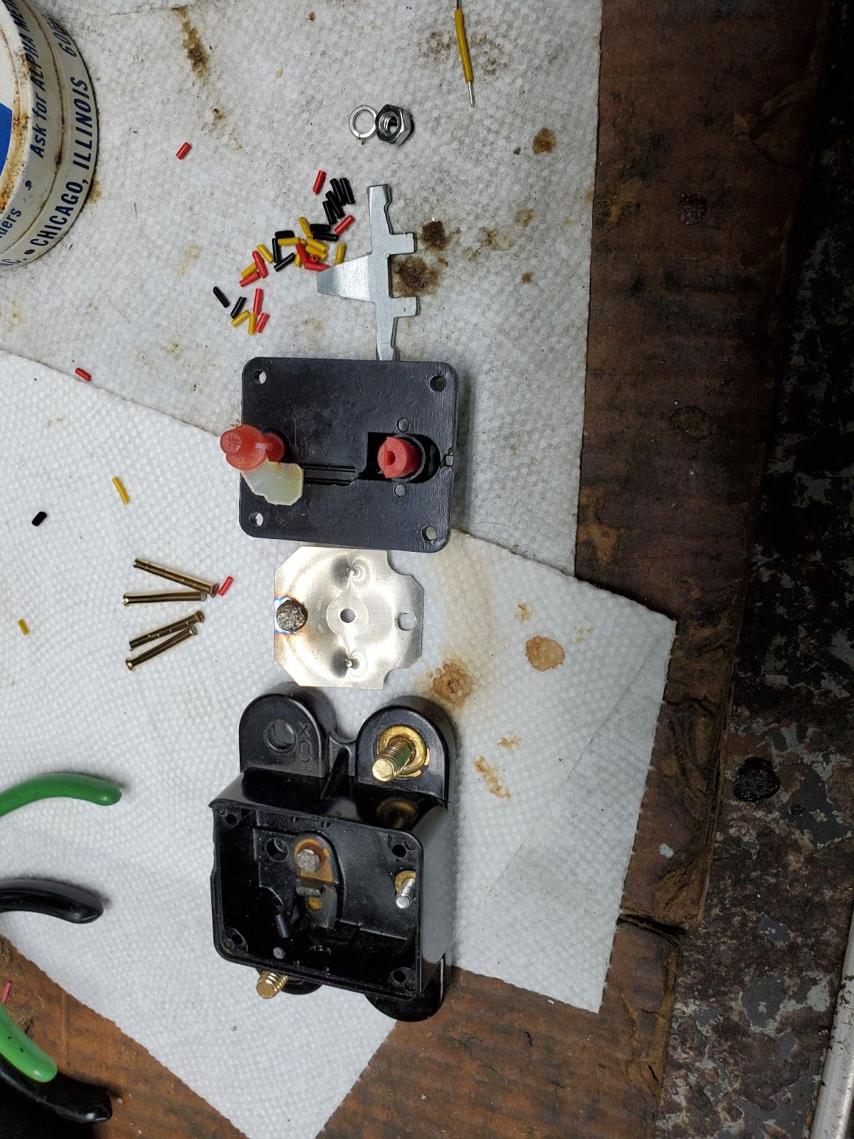
I used a Dremel tool to remove the heads of the four rivets holding the old 250 Amp circuit breaker together. When I disassembled the breaker and viewed the contacts, I was very surprised at what I saw. They were burnt to a crispy crunchy, no viewable metal, only a black uneven surface, that I am assuming now is not a conducting surface.
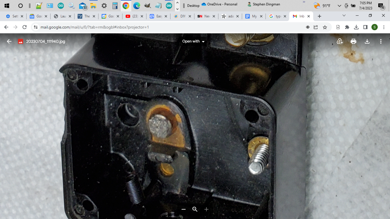
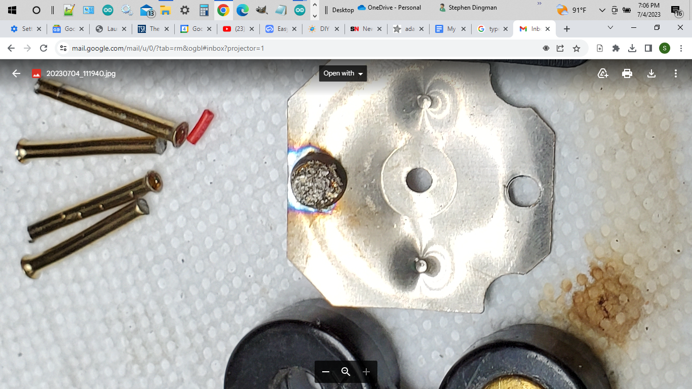
These contact pads are pitted badly. I’m amazed that any current could go through them in this condition.
I wonder if monitoring the voltage across the circuit breaker could be an indication of how clean the contacts are. If the voltage is low then the contacts are very clean and there isn’t anything burned to cause a voltage drop, over time I would think that the voltage across the breaker would slowly grow.
So my 1st lesson is that Circuit Breakers fail, and 2nd, fail in a way that you wouldn’t expect. Mine failed without even opening the Circuit Breaker. My 3rd lesson is the effect a bad circuit breaker has on an inverter. The internal current spikes caused by the cycling power caused internal fuses to Blow. I’ll have to verify that the internal fuses are blown.
I had an idea. I thought it was a good idea. I’m curious about Solar Power. I thought I’d stick my toe in the water and bought a Harbor Freight solar kit. I needed some batteries, but I didn’t want to spend a lot of money so I went to a battery dealer that also recycles them. I found such a business and bought 4 used (AGM) or Absorbed Glass Matt batteries for $100.00 each. They were 100 Amp-Hour Deep Cycle batteries. So I used 0000 AWG heavy wire to place them all in parallel, to make a single 400 AH 12 v Deep Cycle battery. I also didn’t know how close they were to their end of life. The Harbor Freight kit was only a set of 3 - 12 v 15 Watt solar panels and a 12 v Charge Controller. There was no inverter, so I bought a Samlex 12 volt, 3000 Watt. I bought a Skorpion 250 Amp circuit breaker to go between the positive battery terminal and the positive input to the inverter. It worked great until the batteries got low and I would have to shut off the inverter. I needed to know more about the condition of the batteries so I bought a Bogart Engineering TM2030A Battery Monitor. It has an RJ-11 6 conductor phone line connector that sends all of the battery data out by ASCII code at 2400 baud.
I thought I had a decent system that ran what I wanted it to run for a while, but I always had to be there to turn it on and off. It got to be a hassle. So I set up the Arduino Uno, then Mega to monitor the battery data. At first I hard coded the sketch to turn on a mini 5v relay to connect the power switch of my 12 v inverter when the batteries got to 98% and shut off at 95%, then later the pin 1 and 2 of the Remote Start terminal connector on the 24 v inverter. Added transformers to monitor both the grid voltage and inverter voltage, and then Current Transformers to monitor the grid current and the inverter current. Later made the control variable selectable and made Turn-On and Turn-Off Set Points all settable.
The 12 volt inverter started to cut off. I would check the data to see what current was flowing at the cut-off point and what was the battery voltage just before the inverter cut off. I had myself convinced that since the batteries were used, I couldn’t trust them. So when the inverter cut off, I assumed that the battery voltage had dropped to below the 10.00 Volt minimum. I surely didn’t see any voltage readings of below 10.00 volt. I also didn’t see any spikes of output current that would be an issue for the input to the inverter.
Then one evening towards the end of the life of the Samlex 12 volt 3000 watt inverter, I left the system on Automatic pilot all night. The Circuit Breaker would make contact, then break the contact time after time, without the Breaker actually physically opening the circuit, and stay open. This internal switching was causing internal current spikes in the inverter, which I believe blew every one of the internal Fuses. I don’t know if this is true, I need to look at them. I haven’t torn the 12 volt inverter apart yet. I thought, If I’m to buy a new Inverter, it must be a 24 volt one.
So that’s when I ordered the new Samlex 24 Volt 3000 Watt with the Remote Start Terminal. I also ordered a new Scorpion 250 Amp Circuit Breaker. The difference was like night and day. The inverter stayed on.
I used a Dremel tool to remove the heads of the four rivets holding the old 250 Amp circuit breaker together. When I disassembled the breaker and viewed the contacts, I was very surprised at what I saw. They were burnt to a crispy crunchy, no viewable metal, only a black uneven surface, that I am assuming now is not a conducting surface.
These contact pads are pitted badly. I’m amazed that any current could go through them in this condition.
I wonder if monitoring the voltage across the circuit breaker could be an indication of how clean the contacts are. If the voltage is low then the contacts are very clean and there isn’t anything burned to cause a voltage drop, over time I would think that the voltage across the breaker would slowly grow.
So my 1st lesson is that Circuit Breakers fail, and 2nd, fail in a way that you wouldn’t expect. Mine failed without even opening the Circuit Breaker. My 3rd lesson is the effect a bad circuit breaker has on an inverter. The internal current spikes caused by the cycling power caused internal fuses to Blow. I’ll have to verify that the internal fuses are blown.