diy solar

diy solar

Failed Inspection - need some advice and guidance for NEC 690 infractions.

Hmmm...I didn't honestly think about that. Seems far too obvious honestly. I know that if I do that, or whatever I'm "supposed" to do, it won't make a bit of difference to the grounding I already have in place. If it gets this guy off my back, then I may just do it. Thanks for the suggestion! I have tons and tons of ground wire laying around :)
I thought I posted this a few messages back (#71 now that I went back and searched). Make sure to not double tap the lug unless it's explicitly listed for multiple grounds.

I don't know if it's your working/communications style, or fluster from unexpected issue coming up. But you seem to be overreacting / somewhat all over the place.

If you follow the canonical advice being given here (and I would suggest that you collate and organize it on your side, perhaps give a periodic text snapshot of written notes or screenshot of visual notes), then you probably will only get 1-4 minor notes from the inspector across 1-2 more return trips. You could also post back here with incremental progress pictures to confirm that you are following the golden path. When I do these projects as an owner-builder I really do not want to put more work on the inspector than they have to for a contractor.

The first time I had an electrical inspector it was embarrassing, I didn't have all the tools & papers ready, and they only budget 15 min per house... Plus they have a quirk where they want you to torque specific terminals. That was an instant fail and kind of unhappy afternoon, but I passed after the following one.

Compared to those of us that front-loaded the code research before buying or cutting anything, you're probably doing comparable amount of work, except you deferred it and are now catching up. So it's not a big deal. Based on what I saw you're not out that much $$ except maybe those IMOs and some conduit fittings. You're not in a true horror story like being forced to rip up buried conduit.
 
If you won't hit anything a single sectional ground rod that can be 16' or deeper is superior to multiple 6'-8' ground rods since it is more likely to be moister deeper down. They are regular ground rods that are threaded on the end and you use a coupler to screw the next ground rod on to the one you pounded into the ground already. So my ground rod is at least 16' down.
 
If you won't hit anything a single sectional ground rod that can be 16' or deeper is superior to multiple 6'-8' ground rods since it is more likely to be moister deeper down. They are regular ground rods that are threaded on the end and you use a coupler to screw the next ground rod on to the one you pounded into the ground already. So my ground rod is at least 16' down.

How would the inspector know it's really that far down?
 
How would the inspector know it's really that far down?
I've heard stories where some inspectors force you to dig up horizontal ground rods and conduit if you don't let them see the depth before burial... this is where being a contractor and knowing how to deal with borderline official behavior has a big value-add. Lol.

In my town they're OK with photographic evidence. I imagine you could record a video of the 16 ft grounding rod getting driven in.
 
So, let me make sure I have this straight..

Being as he is off grid / building his own new house.. he needs two rods or a fancy as* way of verifying the resistance of his single rod. All houses / buildings with their own separate electric connection to the grid or offgrid would need / normally have this setup I'm assuming. If a separate building is getting it's power from some other building, that has said rods somewhere in the circuit and the distance is appropriate, you would just ground back to the other building and not put in any more rods at that location.

2 legs good! 4 legs bad!
Actually no. All the rules that apply at the main power building also apply to the remote building, as far as grounding electrodes go. You must feed your remote building with a circuit that has a ground wire, and that wire must be attached to new grounding electrode(s) at the new location.
 
Actually no. All the rules that apply at the main power building also apply to the remote building, as far as grounding electrodes go. You must feed your remote building with a circuit that has a ground wire, and that wire must be attached to new grounding electrode(s) at the new location.

I see too much conflicting information on this. I believe that was the old rule of thumb, before they realized that it was bad to put another ground rod at the sub-location. I think Mike Holt says this is unnecessary to outright potentially bad in one of his videos. It seems as though a bunch of old electricians and inspectors still think it's a good idea though and recommend/enforce it.

EDIT, DISCLAIMER : I'm only explaining my understanding of it having read so many threads on here and watching videos by Holt. I have no field experience or certification/training on this issue.. or any issue. LOL
 
I see too much conflicting information on this. I believe that was the old rule of thumb, before they realized that it was bad to put another ground rod at the sub-location. I think Mike Holt says this is unnecessary to outright potentially bad in one of his videos. It seems as though a bunch of old electricians and inspectors still think it's a good idea though and recommend/enforce it.
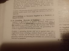
The auxillary electrode at a light pole, let's say, is what Holt was referring to. I've seen the video. A separate building is required to have a grounding electrode system like any other building, with one exception. Here's the code:IMG_20230808_224814193.jpg
 

Attachments

  • IMG_20230808_224749587.jpg
    IMG_20230808_224749587.jpg
    193.9 KB · Views: 4
If you won't hit anything a single sectional ground rod that can be 16' or deeper is superior to multiple 6'-8' ground rods since it is more likely to be moister deeper down. They are regular ground rods that are threaded on the end and you use a coupler to screw the next ground rod on to the one you pounded into the ground already. So my ground rod is at least 16' down.
It doesn't matter how long it is. A single rod means you have to prove it's resistance to earth. If you can't do that, a second rod can be installed and you're done, no proof required. It's like magic. It works so well that electrical contractors just install two rods by default because the inspector can't argue.

The 25 ohms or less and the magic second rod have been the code since at least 1915. But it wasn't until relatively recently that inspectors got wise to it. I remember in the early 2000s when it was suddenly a big deal in the Atlanta area. For years before that, a single rod got the job done, no questions asked. Then, almost overnight, every inspector in everything jurisdiction was hot to red tag a single rod.
 
I see too much conflicting information on this. I believe that was the old rule of thumb, before they realized that it was bad to put another ground rod at the sub-location. I think Mike Holt says this is unnecessary to outright potentially bad in one of his videos. It seems as though a bunch of old electricians and inspectors still think it's a good idea though and recommend/enforce it.

EDIT, DISCLAIMER : I'm only explaining my understanding of it having read so many threads on here and watching videos by Holt. I have no field experience or certification/training on this issue.. or any issue. LOL
All building structures with a multiwire feeder require a ground rod at that building.

N-G bond on my acreage is at the meter pole. There is a service panel with breakers located there and multiwire feeder circuits go to each building on the property. Each building has a ground rod or ufer ground for the breaker panel in that building.
 
The auxillary electrode at a light pole, let's say, is what Holt was referring to. I've seen the video. A separate building is required to have a grounding electrode system like any other building, with one exception. Here's the code:

So.. if the separate building / "structure" has multiple circuits or a breaker box they want a ground rod at it.. probably 2, with 6' between them. If it only has one circuit and ground wire of proper size is run for that circuit, it doesn't need a rod.
 
@meager

I just wanted to say thank you for sharing this experience. Such a situation can be embarrassing, and kudos to you for getting over that and posting this. Your situation certainly can be resolved, even if it will be a bit of work and $$. Your courage in posting it here will help a lot of us, and you too will/are learning a lot.

In my own situation, I am about to fire up my 'power plant' , (battery, inverter, charge controller, appropriate subset of PV) on a cart in my driveway this weekend. If that works, the next step is to wire up the barn where the system will be installed. Your issues have helped me eliminate certain wiring solutions, for which I am grateful.
 
So.. if the separate building / "structure" has multiple circuits or a breaker box they want a ground rod at it.. probably 2, with 6' between them. If it only has one circuit and ground wire of proper size is run for that circuit, it doesn't need a rod.
Pretty much sums it up.
 
That simple metal box better have the proper UL stamps on it!
I don't think the IMO plastic case is a problem as it is UL listed. Metal enclosures are NEMA rated, very few manufacturers of metal enclosures have the NEMA standards built box certified to UL.

Looking at 690.15(B)(4) we see that if a device is listed for the intended application then it meets the requirements. As the IMO is listed for the intended application, then it should fall under this requirement.

The easy way to find out if it will pass is to ask the AHJ about it.
 
Again, your missing the forest for the tree's. You have clear UL9540 violations in a NEC2020 adopted state.

Make the inspector happy, regardless of what is wanted right or wrong and move on. If you fight this, your protentionally forcing having more knowledgeable people review your installation and then you could be in a world of hurt financially and could cost literally tens of thousands replacing inverter/battery to be NEC2020 compliant.
 
I don't think the IMO plastic case is a problem as it is UL listed. Metal enclosures are NEMA rated, very few manufacturers of metal enclosures have the NEMA standards built box certified to UL.

690.31(D) which requires pv system dc circuits to be in metal raceway and boxes would restirct using a pv disconnect in a plastic box in side a building.
 
I don't think the IMO plastic case is a problem as it is UL listed. Metal enclosures are NEMA rated, very few manufacturers of metal enclosures have the NEMA standards built box certified to UL.

Looking at 690.15(B)(4) we see that if a device is listed for the intended application then it meets the requirements. As the IMO is listed for the intended application, then it should fall under this requirement.

The easy way to find out if it will pass is to ask the AHJ about it.
In my experience, asking the AHJ about stuff like that might bring something to his attention that is best left alone. Especially if he doesn't know the answer. The ego of the dictator that lives inside people with authority will not allow them to appear ignorant.
 
@meager

I just wanted to say thank you for sharing this experience. Such a situation can be embarrassing, and kudos to you for getting over that and posting this. Your situation certainly can be resolved, even if it will be a bit of work and $$. Your courage in posting it here will help a lot of us, and you too will/are learning a lot.

In my own situation, I am about to fire up my 'power plant' , (battery, inverter, charge controller, appropriate subset of PV) on a cart in my driveway this weekend. If that works, the next step is to wire up the barn where the system will be installed. Your issues have helped me eliminate certain wiring solutions, for which I am grateful.
This was my hope for sure...to help others, while at the same time getting educated. This isn't embarrassing at all to me though. I got myself in a sticky situation due to my ignorance and I'm working my way out of it. The best I can tell, DIY solar is becoming quite the trend and people need to be able to accomplish energy independence themselves on a reasonable budget. I'd say my systems is pretty basic and of small to medium size, but if I were to hire this out, I was quoted from 80k - 100k+ and at this point I'm all in at about $35k. That includes EVERYTHING...all of the components, solar ground mount and panels, wiring, trenching, tools, power shed, etc... It can be accomplished on a budget for sure. I wish I would have documented my journey better, but I'm a bit lazy on that forefront. And, as it turns out, I would have been giving out very misguided information. When the bank came out to appraise my land before they started the house build, they appraised the solar alone at $85k alone, which really helped me out so I don't have to be so cash strapped.
 
@Nobodybusiness There isn't a ground lug in the inverter. AC in ground (which I'm not using) and AC out ground. I am obviously using AC out ground to the load center. I just got a response back from a tech where I purchased my equipment. I've forwarded it to the inspector and hope to hear back soon. Sometimes it takes a day or so for him to respond. I've also asked the inspector that if I took a picture, would he circle what is wrong with the picture. Someone else made that suggestion on this thread and I thought that was a good idea. It relieves the inspector from making any suggestions, which they are NOT allowed to do apparently.

From the tech:
That article is from 2009. The NEC handbook has been updated many times since then. I cannot find this code anywhere, besides from that article, that requires an inverter have 3 ground terminals. 690.43 also has been changed in 2023.


690.43(C) Location. Equipment grounding conductors shall be permitted to be run separately from the PV system conductors within the PV array. Where PV system circuit conductors leave the vicinity of the PV array, equipment grounding conductors shall comply with 250.134.


The case is bonded to the grounding bar, which is connected to the ac input and output ground. If you have both of these connected properly, and the PV array, using grounding clips and following the code, then everything should be propely bonded.


Do they have an updated NEC code book where they can show me to which code they are referencing?
I just got an email back from my inspector concerning this information. I am asking for a "YES" or "NO...and based on this very lame answer, I truly don't think he knows the answer to this inquiry. He isn't even willing to circle a picture I provide to him and show where it hurts.

Response from the inspector: "I appreciate you digging into these issues. I can tell you care about your installation but you will need to consult with someone else, that is not my role. When you are ready for an inspection, I will come inspect."
 
Is there anyone else in this forum that has the EG4 6500ex with split phase output that has been inspected and passed? NON grid tied preferably. Any chance you can share some pics of your ground wiring?
 
Back
Top