Trip.Diamond
New Member
- Joined
- Nov 15, 2021
- Messages
- 36
Kind of late to the party here but after skimming the answers others have given didn’t see exactly the answers I have given below. My apologies if I missed it somewhere else.Quick background. I live in central Colorado with plenty of land and it is completely off grid. I've been building out my ground mount solar system for the last several weeks and thought everything was going great. That is, until the inspection...of course. I'll try and keep this post as concise as possible and hope for some input. Hopefully, some of my failures will help others as well.
This systems is working far beyond my expectations so far and I'm very thankful for that. I just cannot get this inspector out of my hair and I need to lean on some experts here.
Why am I getting my off-grid system permitted and inspected? Apparently, in Colorado, it is a MUST. Essentially, I cannot build my home without a permitted system.
I have probably already lost a few readers, so I'll highlight the 3 major infractions right here, and add more details below.
- PV system DC circuits that exceed 30VDC run inside a building shall be contained in a metal raceway. 690.31 D
- Equipment grounding conductor shall be run with the PV source conductors and the bonding requirements of 250.97 apply with voltages over 250V, exposed non current-carrying metal parts of PV electrical equipment and enclosures shall be connected to the equipment grounding conductor. 690.43
- PV source conductors operating at voltages over 30VDC and readily accessible must be gaurded. 690.31 A
Here is my "point to point" that was submitted and approved. I had to make some minor adjustments along the way before it was officially approved, but everything is reflected in the diagram. I wired it EXACTLY to specifications detail in this point to point. The only variance is that I added a 400amp busbar for the battery connections. The inspector didn't give two craps about any of the battery side of things. I think I could have wired them together with coat hangers and bubble gum and he wouldn't have batted an eye.
View attachment 161586
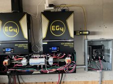
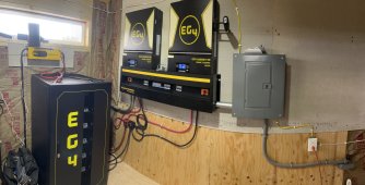
Here is a pic inside the powershed from a few days ago when the it was fully wired up ready for inspection. Ignore the exposed AC outlets...its still a work in progress.
View attachment 161596View attachment 161605
Here are the 12 items I failed on. Most of them are super easy fixes and simple oversight on my behalf. #3, #4 and #5 are fairly major.
- Back-fed inverter output breaker in AC panel, tie down required 408.36 D
- Fixed this by ordering a Homeline Back-Fed Main Breaker Barrier from Home Depot
- Green bonding screw required in inverter output panel. 250.28
- Whoops. Total rookie mistake. Fixed this by installing bonding screw that was just sitting in the panel
- PV system DC circuits that exceed 30VDC run inside a building shall be contained in a metal raceway. 690.31 D
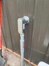
- OMG! Seriously? I've yet to see an online video where the entirety of the PV DC circuit is encased in metal from the point of entry. Most installations are very similar to mine. I've used liquid-tight for everything and it all needs to be replaced with metal conduit...including my 1-1/2in Sched 80 entry and junction box. I've done my best to figure out an exemption for this, but I can't find one. I have to assume that others here have come across this. I still haven't figured out how / where to transition from PVC to MC. This is going to be quite a cluster indeed.
- Equipment grounding conductor shall be run with the PV source conductors and the bonding requirements of 250.97 apply with voltages over 250V, exposed non current-carrying metal parts of PV electrical equipment and enclosures shall be connected to the equipment grounding conductor. 690.43
- This one has me very puzzled and I need help...please! I simply cannot figure out exactly what the infraction is. I try to get answers from the inspector, but he simply cannot / will not offer any suggestions. He basically says "refer to the NEC handbook for the code". He claims there needs to be an additional ground wire from the inverter to the common ground. The EG4 6500's only have AC-in ground and AC-out ground. I have AC-out ground going directly to the load center as illustrated in the above point to point, which ultimately goes out to earth ground just outside the shed. I know for fact that the inverter case is fully grounded. We even did a continuity test to prove it was when he came out. I even had some back and forth emails with a Signature Solar technician and he has no clue what to think of it.
- The inspector did email me back for this infraction and referred me to this posting as a reference on how to "fix" this infraction, but reading it leaves me even further in the dark.

Connecting the Inverter
iaeimagazine.org
- PV source conductors operating at voltages over 30VDC and readily accessible must be guarded. 690.31 A
- This infraction is in regards to the very small length (less than 1ft) of PV wire I have "exposed" from the top of the DC disconnect to the bottom of the inverter. I didn't know it needed to be "guarded". Apparently, this does NOT have to be metal conduit based on the very vague answer he gave me when he was on site. All of this "guarding" is going to make it difficult to rearrange stuff when I either see fit to do so...or worst case, in an emergency where I have to move stuff around for various reasons. Not cool at all!
- Show ground lugs at array are listed for PV 690.43 B
- I cannot find evidence that the ones I ordered on Amazon are listed...so I have to replace all 20 lugs with "listed" lugs. Lame!
- Show OCPD's are listed at array. 110.3
- Turns out that Amazon is not a good place to find listed DC breakers. The DC breakers I have in my point to point above (at the array) where shot down because they only meet the IEC60947-2 standard. They are NOT listed and I have to order new ones that are. That being said, I guess avoid purchasing these breakers if you plan on getting your system inspected.
- View attachment 161618
- PV source voltage and current label required at locations listed in. 690.53
- I have tons of PV stickers, I just didn't know exactly where to put them. Now I do...sort of. I get the idea behind the stickers, but I assure you I've yet to meet a fire fighter that is going to take the time to read them.
- AC output voltage and current label required. 690.54
- Same as above (#8)
- Light over AC panel required inside power shed. 110.26 D
- Although I certainly planned on adding lighting inside the shed, I didn't realize it was a requirement. I'll just add a light before next inspection.
- Supplemental grounding electrode required at power shed 690.47 (250.53 A 2)
- Once again, this is an example of my diagram passing with the inspectors blessing, but when he showed up onsite, he failed for it. I went ahead and added a supplemental rod 8 feet from the other ground rod just outside the power shed.
- Drive ground rods flush or below grade. 250.53 A 4
- Easy fix. Just hammered to flush.
#3. Liquidtight comes in two different forms. Metallic and Non-Metallic. Metallic or LFMC conduit is generally acceptable as is Flexible Metal Conduit or FMC (although they may require bonding bushing for Grounding purposes). Non-Metallic Liquidtight is not acceptable.
#4. Short answer – He wants to see a Grounding Lug or Ground Bar in the EG4 6500EX’s with Ground Wire from the Array tied directly to it.
Long(er) answer – The article he sent you to is from 2009! And way out of date with current Un-grounded PV-systems like the one you have installed. (not Equipment grounding conductor - you still need those!)
That said what I believe he is telling you is that the Continuity check you can demonstrate is not enough to satisfy him that a Solid Bond has been made between ground and the case of the 6500EX’s. He wants to be able to see bond directly to the Case.
Adding a Listed Grounding Lug or Bar in each 6500EX, and attaching the Array Ground wire to it, may be all he wants you to do. It’s not uncommon to have to Add a Grounding Bar to an Electrical Cabinet or Box. Absolutely no guarantees though. He could then just complain that you “modified” the Inverter and still disallow the install.
#5. The wires from your disconnects to the 6500EX’s must be in Conduit. You may be able to use non-metallic here but maybe not. (I believe Zwy pointed this out)
#6 Unfortunately Amazon does not sell any Listed Ground Lugs. You have to make sure they are rated to UL-2703 standard. (ran into this one myself and yes the only difference seems to be the 10X times price!) They do need to be able to bond dissimilar metals outdoors though so kind of important.


