diy solar

diy solar

Failed Inspection - need some advice and guidance for NEC 690 infractions.

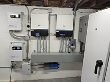
So, I'm wondering, what is it specifically that keeps something from being run from the raceway to the bottom cabinet of the inverter (e.g. FMC) ? What if the inverter has fans along bottom right where the 48vdc comes through?
Oh, I suspect that would be fine. In my case all fans were back away from that bottom raceway so it made most sense to just attach directly to it.
 

30A, 600V AC/DC, outdoor. This one is $200
you have to study the safety disconnect switches from squared D to find the ones that are rated for DC....
I have bought several used in excellent condition for a fraction of the new retail price, but you have to look at and read all the labels etc....
some of these are huge, some are only indoor-rated and some are outdoor-rated etc..
but the best are outdoor rated and if you get the larger ones say 100 amp for less than 100 bucks you have definitely scored a bargain>>> if it is DC rated for 600 volts DC... and they are in good functional condition...
I like square D and square D QO products....

1706466158503.png
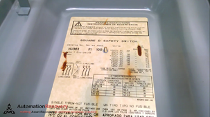
I bought this Square d HU363 100 Amp safety disconnect switch for 91 dollars including tax and delivery. It is rated for 250 volts DC.

1706466297462.png
For DC you can use the inside and outside poles of the switching mechanism for 250-volts DC.... this was rated for indoor use but I will use it indoors as a manual disconnect....
I believe that using only the inside and outside poles gives a little more separation for the DC wires to aid arc flash safety issues.... as a lot of these switches have that direction on their labels when used for DC...
large and somewhat of an overkill but superior to the plastic garbage out there...IMHO

I am always leery of el-cheapo Chinese breakers and disconnects....so I avoid them as much as possible
 
Last edited:
I've already sent the inspector pictures of what I think needs to be replaced, but he will not respond to those emails. I think that falls into the "suggestion" category. This is absolutely like pulling teeth when trying to get information from the inspector. I don't know if they have a god complex, but it seems it would be beneficial to the homeowner (me) to just tell it like it is rather than being super vague. I just want to know what I need to do and do it safely. This NEC code stuff isn't that easy to follow. I'm a software engineer and I cannot imagine throwing "hints" of my trade to an electrician. I've asked him to share another point to point that did pass inspection, but so far it's just crickets on that. I cannot imagine why the state wouldn't just post this information as help to the DIY'er. It's not like it's proprietary information.
If the inspector suggests something and there is an issue later, he has become the now irresponsible designer. If you can develop a clear plan of action on paper and perhaps just ask, "will this pass inspection?" before actually doing it and possibly failing, maybe you will get an answer. This is one of the most educational threads I have read. I am sorry that your errors have led to it, if I lived there I would help you out! I would trade for some software engineering ;)
 
Of course there is the "move to Texas" option ... heck - as long as you are not in a city or a major town the only advice the inspector will ever give you - over the phone because they aren't coming out - is "don't do anything stupid to get yourself or someone else killed -- and don't start a fire" ... and when your finish if you have time - take a picture and send it to me ... LOL
I want to move
 
Unfortunately I didn't read through all 9 pages to see where this has all gone, but to give you some added empathy I also had to go through some of the steps you're having to do because of inspection, all the while being jealous of the other installs where some of the things I feel give no added safety in the first place could be skipped.

View attachment 161930

My local inspector also made me do some things that I'm 80% weren't needed in the latest version of code but weren't worth me fighting, such as using rigid conduit on my underground sections and not allowing me to run my 48V cables inside the raceway with my AC runs, but still requiring it to be in metallic. That liquid tight is metallic. But yes 100% of my high voltages lines are in metal 100% of the time after leaving the array.
any 110-26 violations?:rolleyes:
 
Power conductors of AC and DC systems rated 600V or less can occupy the same raceway, cable, or enclosure if all conductors have an insulation voltage rating not less than the maximum circuit voltage [300.3(C)(1)].Feb 17, 2011
Please know that in some areas, they may have a code addendum, like San Francisco, that may still disallow mixed conductors though the same insulation value.
 
I believe, even if independent parts are UL listed, the combination of them must also meet UL. The ensuing disconnect/switch would not be a UL listed assembly. Is this incorrect?
It depends.

If the parts are RU, absolutely not.

Preassembled combination of UL following manufacturer instructions is a gray area. There are companies that package together kits for electricians or pre populated wiring boxes and sell those with value add. As well as companies that put together controls panels that are themselves UL listed. The latter can require a certification at the workshop level to make it legal.

The bundled kit is definitely legal to sell. The preassembled kit… now I’m not sure where the boundary is between that and a UL panel shop. Maybe it’s like 🦵, where you know it when you see it

For UL9540 AC ESS the required listing is on the combined system. For the mythical DC ESS it can be a composition of listed constituents.
 
Absolutely.
I wouldn't install an auxiliary rod at the array, unless I was forced to.
And it would be disconnected, as soon as the inspector was out of my driveway.

Please explain the logic so I understand?

From all my reading on antenna masts and other outdoor electrical/electronics they want a ground rod as close as possible to the item that may draw lightning and then a fair sized unbroken wire running to the common house ground. The idea being that lightning travels slower in the ground than in a copper wire.

When a lightning bolt strikes the potential at the strike point raises to several hundred thousand volts and as it travels in ground it raises the potential to a lesser amount as distance increases. Without the ground rod and wire to conduct the bolt you end with the array at high potential and the house at normal potential so you get arcing through electronics to ground at the house. Then back to a normal potential at the array while the houses raises to a high potential and things arc back towards the array. A double whamy in a matter of pico seconds.

With the rod and wire (size depends on distance) both the rod and array are always at the same potential, it may be a couple hundred thousand volts, but relative to each other they are the same. Relative to each other and no arcing through your equipment. The transformer at the pole may blow a fuse or explode, but your house is good.

This information all comes out of the Motorola spec for grounding antennas for radio transmission. Another part of the same document says to use ground rods along the length of the wire cold welded to the wire. Cold weld can be crimped or other method seal out moisture and air. The number of ground rods depends on length between points. For example 16ft would require 2 x 8ft rods, one at either end. 32ft would be one at either end and one in the middle. 48ft would be one at either end and another every 16ft along the way.

I came across all of this after direct strike to my weather station mast. Blew threw about 10k of electronics and sounded like a bomb went off outside the window. My mast is 30ft tall and the run around the house is 50ish feet. I used bare copper stranded #2 wire that I had on a spool. Down the inside of the mast to a ground rod at the base and around the house to the main panel ground. According to doc I could have used #8 wire but I had the spool from when a friend moved and he gave it to me in exchange for hauling car parts to the dump.

There are other things that it says on the subject and I am wondering why it wouldn't apply to solar arrays. I assume some of this is where the NEC requirements for 2 ground rods comes from.
 
Last edited:
Please explain the logic so I understand?

From all my reading on antenna masts and other outdoor electrical/electronics they want a ground rod as close as possible to the item that may draw lightning and then a fair sized unbroken wire running to the common house ground. The idea being that lightning travels slower in the ground than in a copper wire.

When a lightning bolt strikes the potential at the strike point raises to several hundred thousand volts and as it travels in ground it raises the potential to a lesser amount as distance increases. Without the ground rod and wire to conduct the bolt you end with the array at high potential and the house at normal potential so you get arcing through electronics to ground at the house. Then back to a normal potential at the array while the houses raises to a high potential and things arc back towards the array. A double whamy in a matter of pico seconds.

With the rod and wire (size depends on distance) both the rod and array are always at the same potential, it may be a couple hundred thousand volts, but relative to each other they are the same. Relative to each other and no arcing through your equipment. The transformer at the pole may blow a fuse or explode, but your house is good.

This information all comes out of the Motorola spec for grounding antennas for radio transmission. Another part of the same document says to use ground rods along the length of the wire cold welded to the wire. Cold weld can be crimped or other method seal out moisture and air. The number of ground rods depends on length between points. For example 16ft would require 2 x 8ft rods, one at either end. 32ft would be one at either end and one in the middle. 48ft would be one at either end and another every 16ft along the way.

I came across all of this after direct strike to my weather station mast. Blew threw about 10k of electronics and sounded like a bomb went off outside the window. My mast is 30ft tall and the run around the house is 50ish feet. I used bare copper stranded #2 wire that I had on a spool. Down the inside of the mast to a ground rod at the base and around the house to the main panel ground. According to doc I could have used #8 wire but I had the spool from when a friend moved and he gave it to me in exchange for hauling car parts to the dump.

There are other things that it says on the subject and I am wondering why it wouldn't apply to solar arrays. I assume some of this is where the NEC requirements for 2 ground rods comes from.
This has nothing to do with a direct lightning strike.
That would be lightning protection. (A completely different system)
This is about the electrical safety grounding system.
This is in regards to the gradient pulse generated by a nearby lightning strike.
I don't want to give that a quick path to my equipment or household appliances.
I want it to dissipate over distance in the earth.
 
This is in regards to the gradient pulse generated by a nearby lightning strike.
I don't want to give that a quick path to my equipment or household appliances.
I want it to dissipate over distance in the earth.

If you want to protect against lightning strike, stand a lightning rod above the thing to be protected and run a ground wire separate from building's grounds all the way to ground rod in Earth. Or multiple lightning rods, with wire draped between them, to protect something larger.

So for protection from lightning current in the earth, how about building a "fence" of lightning rods around the facility, joined by copper? Trying to give it a low impedance path around.

But how deep into the earth might it dive, and come back up to the building? Or is there skin effect for the earth?
Possibly similar to the issue of underground drainage, keeping water from rising up to form a spring within the structure. But that analogy is only for DC, not so much a pulse.
 
If you want to protect against lightning strike, stand a lightning rod above the thing to be protected and run a ground wire separate from building's grounds all the way to ground rod in Earth. Or multiple lightning rods, with wire draped between them, to protect something larger.
Exactly
Lightning protection is a separate system.
Designed to route the strike around the equipment that you want to protect.
(Definitely not to, or through the equipment that you want to protect)
 
Exactly
Lightning protection is a separate system.
Designed to route the strike around the equipment that you want to protect.
(Definitely not to, or through the equipment that you want to protect)
I finally understand this. We rarely even see lighting, I have never done lightning protection, but I do see how auxiliary ground rods can cause problems if lighting does strike..Thanks for being persistent with this.
 

diy solar

diy solar
Back
Top