diy solar

diy solar

Surge supression

lapsmith

New Member
Joined
Apr 10, 2022
Messages
280
Haven't seen this posted elsewhere. The inverter I ordered (Growatt MIN11400) says it has class 2 DC surge protection. My solar panels will be about 100 feet from the inverter on the roof of a barn. Should I add another supressor such as the Midnite Solar? Midnite Solar says to install their supressor at the input to the inverter. If I add a surge supressor, should it be near the array, or at the inverter? I would expect having two supressors in parallel would increase the protection?

Midnite Solar's website says their 600 volt version can handle currents with a 8/20us wave form. As far as I can tell, a class 2 supressor is the same, however I can't find how much energy the Growatt can handle vs the 2160 joules of the Midnite solar. Any thoughts?
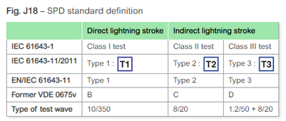
1703689768390.png
 
SPD's should be placed near the equipment and appliances that you want to protect.
Generally between the equipment and the point where the wires enter the building.
A lot of companies sell combiner boxes with built-in SPD's. They are useless, if installed 100' away, at the array. At that location, they can only protect the array. But most people don't know any better. So, they buy them, thinking they are going to be protected.
 
You can also buy individual MOV, for a lot less.
They are a replaceable part in some of my GT PV inverters.


Be sure to select a part that isn't conducting any current at your operating voltage. It is not meant to clamp voltage to the spec'd input of your electronics, rather to clip really high, fast peaks. Rated voltage of MOV maybe 50% above your electronics.
 
Thanks, Timselectric, appreciate your help. I'm thinking of forgoing the additional SPD since I just realized I would need four (I have four strings, no combiner).
 
Use 3 MOV, bridging PV+, PV-, ground.
 
TMOV20RP750E has 1980V max clamping voltage. It will not protect inverter AC input. Better choice would be TMOV20RP300E with 300Vrms and 775V clamping voltage if connected across two hot wires. Even better to use 150Vac TMOV20RP150E connected to each hot wire and neutral. But the problem is MOVs have high clamping voltages and are not very good for protecting solid state power transistors from lightning induced transients. Better to use TVS diodes but they are more expensive and less powerful. But TVS provides much tighter max clamping voltage.
 
Even better to use 150Vac TMOV20RP150E connected to each hot wire and neutral.
Mouser has them in stock. But when you say connect to each hot and neutral, I assume you are talking about the AC input. How would you connect them, one from L1 to N, one from L2 to N? Or do you mean from each hot to ground and neutral to ground.
Better to use TVS diodes but they are more expensive and less powerful. But TVS provides much tighter max clamping voltage.
Any you can recommend?

When installing, would you just put them under the clamping screw for the main conductors? I could also look for a way to solder them to the circuit board before I hang the inverter.
 
How would you connect them, one from L1 to N, one from L2 to N?
Never mind, your inverter has no neutral. I need to read descriptions better. Int that case use 750V MOVs on PV outputs at the array side and another set at the inverter PV input side like Hedges suggested. Your inverter will probably bias PV negative conductor to -600V peak referenced to ground due to being non-isolated design. For AC side of inverter you can use 300V MOV across L1 and L2 and 150V MOV from L1 to ground and another 150V MOV from L2 to ground. Assuming you have split phase 120/240V service. Make sure MOVs are all tied to same ground bar so that surge current will flow around the inverter and not trough it. I will have to look up TVS diode spec but you probably can get by with MOV. I am still researching better surge arresting devices than the MOVs. You have to mount MOVs in metal box away from combustibles because they can catch fire if they fail.
 
Depends on what you're protecting.
Maximum DC Volts 970 V, it says. Could be suitable for 600V PV input, or a bit lower voltage one could be used.
Note that testing with low current, the parts SMA selected for their inverters clamped at 1075V.

If the 150Vac rated part is used for 120V nominal, that will wear out sooner from periodic transients.
AC powered equipment should withstand spikes in the kV range, but we're adding extra protection.

What I got myself clamps at a measured 200V, and it has a second slightly higher voltage bank of MOV waiting in the wings in case the first set fails.


Maybe TVS plus MOV will work, with MOV taking some of the energy. Depends on impedance, too; wire inductance and resistance could help split the energy.

To take care of the "fire" problem, you can get MOV with PTC fuse in series. I think that's what Midnight uses, with the 3rd leg enabling either green or red LED to show "protecting" and "failed".


Those are 150VAC. I got others for my 600VDC strings.
I soldered three in a "delta" arrangement with wire pigtails.
 
Note that testing with low current, the parts SMA selected for their inverters clamped at 1075V
That part will allow up to 2kV to develop at 100A. Clamping voltage at 1mA has no relevance to actual peak surge currents during a lightning strike. That's why MOVs are lousy at protecting power electronics and why inverters still blow up from direct or close by lightning strikes. They are good for protecting transformers and motors from winding insulation breakdown. For inverters commercial MOV based SPDs are inadequate IMO.
If the 150Vac rated part is used for 120V nominal, that will wear out sooner from periodic transients.
150V part passes 1mA at 216V which requires 152Vac(rms) to reach and only then on the peaks of AC waveform. Although there is tolerance range for MOVs and they do drop their voltage threshold as they age. Sure you can use 200V part at the cost of increased clamping voltage where it becomes more ineffective at protecting the inverter.
Maybe TVS plus MOV will work, with MOV taking some of the energy. Depends on impedance, too; wire inductance and resistance could help split the energy.
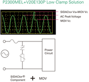
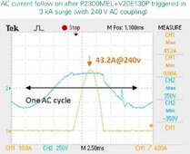
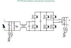
There is interesting solution using Sedactor + MOV (Page 5: PDF link). Much better clamping performance vs. higher voltage MOV by itself.
sidac2.PNG sidac1.JPG pv-sidac.JPG
 
Last edited:
Never mind, your inverter has no neutral. I need to read descriptions better
I wasn't even aware of that until someone pointed it out in another thread. But it does have a neutral on the AC input side, just not the backup output (I have to purchase transfer switch from them which also has a transformer in it which gives neutral)

There is interesting solution using Sedactor + MOV (Page 5: PDF link). Much better clamping performance vs. higher voltage MOV by itself.
Looks good to me. Would I install them at the array as well? I see that they come with a fuse, do you think that is fast enough, or should I still install them in a metal box?
 
Looks good to me. Would I install them at the array as well?
Not sure without knowing what voltage potential your array will be in relation to earth ground. You'd have to probe PV- and PV+ to ground during operation and during idle (night) using high voltage capable oscilloscope and probe. Non-isolated grid inverters can bias PV inputs to 600V peak relative to ground. Selecting MOV or SPD of too low clamping voltage can overheat and destroy it.
I see that they come with a fuse, do you think that is fast enough, or should I still install them in a metal box?
Absolutely. Failure mode of MOVs is blowing apart with fire. Lots of house fires caused by cheap plastic power strips with MOVs catching fire inside.
 
For some reason, I'm missing the latter part of this thread discussion where we talked about checking the voltage on the PV = and - with a scope. Anyway, I will be away for a week, but will do that once I'm back and the system is up and running.
 

diy solar

diy solar
Back
Top