diy solar

diy solar

[FIXED] Careful if you ordered Apexium DIY Box (melted fuse cover)

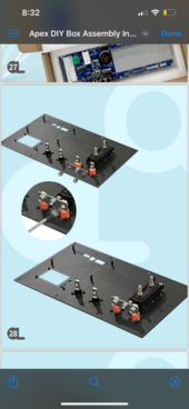
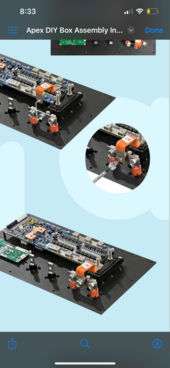
Couldn't resist looking into the manual and I agree with the note from @Lt.Dan about the terminals.

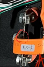
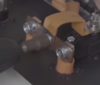
The manual is, imho, wrong here. To me, the busbars should make direct contact to the terminals busbar, and the current should NOT be passing the (fixed) nut. That nut/thread is only to secure the bolt.

That busbar should be mounted exactly the other way, so the bar from the fuse makes direct contact with the busbar towards the terminals.
Can you clarify the positioning a little more?
NOT as in this image where the supporting nut is part of the circuit.

View attachment 193505View attachment 193507

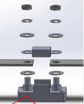
I found a picture in another Apexium thread:
This is how it should be in my opinion, not as in the manual

View attachment 193510

As for the washers: Remove washer C. So the fuse is in direct contact with the busbar. The washers on both sides should 'sandwich' the busbar/fuse, but not be in beween.
Got it thanks
Current is passing the main circuit, busbar on busbar / terminal / fuse. Bolts/nuts/washers are to secure it in place. If there is no other way, use suitable conductive materials. Regular (steel/rvs) washers eg aren't.

When in doubt (And I personally always do on high current installs), run it for 15-30min and check with a flir camera. Any bad connection/resistance will show up very clearly.
Will a heat laser work?
 
I think the busbar only has gotten very hot. Carefully clean, (very) gentle sand the contacts and if preferred renew heatshrink.

I would try replacing the fuseholder and positive terminals (You can buy them separate, if I remember correctly they are Futronics connectors)
I hope I don’t have to buy anything and Docan makes me whole. What a shit show. I need to get this up and running today even if it’s a short temporary workaround. Any ideas of parts that I can run into town instead of waiting for shipping?
 
Wow.
Several issues here...
Looks like the bms was bypassed...
Half the current path ignored, and a scary amount of power was being pulled.
I hope OP responds with photos and explanations of the build before failure...
can you clarify what you mean by the BMS was bypassed and current path ignored?
 
Flip the busbar over, replace the fuse holder (a local autopart store might have a replacement fuse holder).

alternatively you can remove 1 of the terminals and use that hole as entry for a wire, crimp a lug on it and connect it to the busbar from the BMS. (Wouldn't recommend that as final solution off course but it will get you up and running)
 
Both mistakes are not in the Seplos video: the PEM nut is facing backwards, not part of the circuit, and there is NO washer between busbar and fuse. (in their video the busbar is on top of the fuse, but that doesn't matter)
Only advantage of the fuse on top is easier access when you need to replace it.

The image above as posted by @Neil H is how I would recommend it (busbar / fuse or fuse / busbar is equal)
 
Flip the busbar over, replace the fuse holder (a local autopart store might have a replacement fuse holder).

alternatively you can remove 1 of the terminals and use that hole as entry for a wire, crimp a lug on it and connect it to the busbar
Like the main busbar? I would have it go to a 250a fuse in between .

from the BMS. (Wouldn't recommend that as final solution off course but it will get you up and running)
 
Like the main busbar? I would have it go to a 250a fuse in between .

from the BMS. (Wouldn't recommend that as final solution off course but it will get you up and running)
look at the video on assembly, the apexium is just a rebadged seplos mason box
 
My thanks to the OP for an informative Thread. It never hurts to step back and review things to see if they makes sense even if instructed to do something a certain way.
 
The real question is how do I salvage this to get working tomorrow? Should I just skirt the 400A fuse and hook it straight to the BMS? Seems kind of pointless to have a 400 amp fuse on a 280Ah battery.
400A fuse on 280Ah battery is not totally pointless as these batteries can sustain over 500A for at least a half minute and thousands of amps momentarily. Of course wiring and BMS should be also rated for 400A in that case.

For temporary fix I’d clean the contact surfaces of the bus bars and fuse with scotchbrite and assemble fuse holder back together(assuming that fuse holder has some structural strenght left), this time without the washers ”C”
 
So looking at it again it’s not a nut but part of the bar. It just looks like a nut. Do you recommend still putting it on the opposite side?
If I'm seeing it correctly, it does look like an odd connection as illustrated by the pictures in the manual. It appears to limit the contact surface area to a small ring.

If that center insulated bus bar is flexible enough to allow a flat (parallel, not bent or angled) connection on the other side of the cross bar, and if the bolt can pass through it from the far side to the threaded portion on the near side, and if there is no obstruction (that screw in the image that appears to be sticking up on the back side?) to prevent this configuration, then it might be a good idea to move that connector to the inner side of the cross bar. It would mean a much better contact (more surface area) between the cross bar and the insulated bar. Just my opinion as a solar noob with some electrical background.
 
can you clarify what you mean by the BMS was bypassed and current path ignored?
I’m sorry, I misunderstood some of the pictures.

Look at EVERYTHING between the BMS and the overheated parts and be COMPLETELY certain all current carrying components are in direct FLAT TIGHT contact with copper ONLY, no washers, no nuts, NOTHING between conductors and bussbars.
 
The good news is IF the BMS still works, after reconnecting things directly, without washers in between, you have a spare set of terminals, so, with new cables you should be able to get these up and running.
 
Back
Top