diy solar

diy solar

24 VDC and 12 VDC brakes in Fifth Wheel

chrisski

Solar Boondocker
Joined
Aug 14, 2020
Messages
5,192
I am wondering if anyone has installed 24 VDC in a fifth wheel or travel trailer, and how they got their 12 VDC to include electric brakes to work?

The intent of the 24 VDC install is to provide 1200 watts of panels to safely power a 2000 watt inverter. Unfortunately, everything else in the RV to include internal lighting and brakes would be powered by 12 VDC still. I 've seen DC to DC converters by Victron, and something like that would definitely work for all the 12 VDC appliances in the RV except the brakes.

I'm unsure how much power the brakes draw, but I do know they need a battery to operate. If the trailer battery is dead, the wiring from the 7 pin harness won't provide enough juice, and when the trailer battery is completely dead, the tow controller will read "Not Connected," and all braking definitely comes from the truck and not the trailer, as I found out driving with a dead battery. Because of not knowing the surge rating of my brakes, I'm reluctant to simply use a 24 VDC to 12 VDC converter and end up in a no brake situation.

==================
EDIT 21 Dec 2021 (A lot of good stuff in this thread including a buck converter that did not work, but here is what I used.

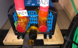
I just finished my 24 volt upgrade and got rid of the 12 volt battery. I installed a single Victron Orion 24 volt DC to 12 Volt DC converter 70 amp converter and things are fine. I have a 2 axle 12,000 LBS fifth wheel and that converter can operate the leveling system which pulls 50 amps at 12 volts and has no problem doing it.
A6D1C506-6A91-4618-ABE3-2A355C03E3E5.jpeg
 
Last edited:
Simplest way is to have a hybrid battery system with a small AGM or FLA. This works great if you have an on-board generator. There are other reasons for a hybrid system, too especially if alternator charging is part of the situation like on a fifth wheel or travel trailer.
Link for hybrid system info -thanks @grizzzman
https://www.zwerfcat.nl/en/lithium-hybrid.html
 
There's no onboard generator or alternator. One of the seven pins from the trailer hook up does provide 12 VDC, but not at a lot of amps. Looking at that diagram this hybrid system is the same volts to all appliances.

I can't find anything on google, and I doubt I'm the first person who needs the power from a 2000 watt inverter leaning towards the safe side wants to power it with 24 VDC and 83 amps surging to 150 amps instead of 12 VDC and 166 amps and surging to 300 amps. I think 300 surging amps through normal sized wires starts to become too hot. I'm saying normal sized because some of the inverters I'm looking at don't have very large wire inputs and running a wire size calculator, the wiring for the inverter is supposed to be a foot or two.

I will look at the optimization if I do upgrade. Would be nice to get 400 ah of lithium batteries.
 
Yes, the diagram is a single voltage domain.

Personally, don't think going to 24v is worth the complexity or the extra cost for driving a ~2000 watt inverter as more clearly explained. Just make sure cabling and over current protection are properly sized for inverter surge plus the normal rv simultaneous loads that will be run.

If the inverter you are looking at can't accommodate the proper wiring/lugs for stated capacity/surge -something is not right.

Strongly suggest looking at a UL 458 listed device -yes these won't be bargain basement cheap, but will have provisions for maintaining proper neutral bonding.
 
24 VDC install is to provide 1200 watts of panels to safely power a 2000 watt inverter.
You know you would have to have a 24v battery and not just power the inverter right?
The rule of thumb that is normally bandied about is 12v until 3000w.
If everything is 12v already, i would be hard pressed to go 24v when some beefier cables from battery to inverter is so easy.
 
You know you would have to have a 24v battery and not just power the inverter right?
The rule of thumb that is normally bandied about is 12v until 3000w.
If everything is 12v already, i would be hard pressed to go 24v when some beefier cables from battery to inverter is so easy.

I did not know that. With 400 AH of battery power, I had been planning with a 1000 watt inverter at 12 Volts, and to power a 2000 w inverter 24 volts, and then 36 Volts would be 3000 watts. Each time the voltage went up, another 600 watts of panels and 4 more 6 volt golf cart batteries to keep the amp hours at 400.
 
That is not how inverters work.
You can buy a 12v 2000w inverter.
It will require larger wire from the battery to handle the increased amps (and bigger inline fuse or breaker).
One does not mix and match voltages as your email suggests (though i really do not understand it).
 
but you are right that sucking more watts will requires a bigger battery to get the same operation time.
You will just add a battery in parallel to the first one to raise Amps, instead going serial and rising voltage.
you can also keep the 12V battery for the brakes and go 24V for the other circuit.
It seems more logical to let the truck manage the automotive part (truck will charge the battery trailer trough the harness).
 
Last edited:
You mention possibly upgrading to “400ah lithium” (assuming 12v here) which would easily handle a 2000w inverter.
What is your current battery setup?
A smaller lead acid battery may struggle depending on size and type.
 
you can also keep the battery for the brakes and go 24V for the other circuit.
That is actually one of the options I am considering, Victron makes a 24 VDC to 12 VDC charger, but it is designed for alternators, and don’t know how it would handle battery input for the 24 VDC. I also wonder how a Solar converter charger would operate if the input was the 24 VDC battery to attache to charge my 12 VDC battery. There’s quite a few 24 VDC to 12 VDC converters, but I’m not sure how the battery charging profile is.

Any of those three cases, I don’t want ot be the first on my block to try.

You mention possibly upgrading to “400ah lithium” (assuming 12v here) which would easily handle a 2000w inverter.
What is your current battery setup?
A smaller lead acid battery may struggle depending on size and type

So I am building my system. I am starting with 12 Volts and I’d like to go to 24 VDC next year.

I have most of the equipment purchased except the inverter and some hardrware like the battery compartment and mounting. I have 4 GOlf Cart Batteries, 6V 229 AH each that will be wired in Series Parallel with 2/0 Welding Cable. I Have 6 solar panels, 100 watts each mounted on the RV roof (unwired) That will be connected with 10 Gauge wire 3S2P. The Combiner will be located next to the battery compartment. The Charge controller is the Victron 100/50. There’s also a Victron 712 battery monitoring system.

I started planning this back in March, and purchasing parts in April. Arizona is just so hot, I had planned on waiting to September to install, but started with a battery charging station at the house last month, and this month is mounting the panels, and perhaps getting the cables drilled through the roof, through my bedroom, through the floor, into where I will put the battery storage compartment. Right now the panels are mounted with Eterna Bond Tape, but tomorrow I will secure the panels with screws, and seal it with Dicor. I have quite a few lessons learned already, the latest is the tilt brackets for the solar panels on my RV in my case are not worth it.

The other forum I was getting my info from was not quite so active and also quite a bit more conservative when dealing with inverters.

This is my first real build, the last was just hooking a cheap MPPT charger to a battery and a 400 watt inverter and calling it a solar charger. I was an electronics technician, but that was quite a while ago.

So any input is welcome, I certainly have a lot to learn and would like to get it right the first time!!
 
What makes you think your DC to DC converter won't power the electric brakes? Some quick Googling seems to indicate the amp draw for 4 10" or 12" electric brakes is 15.0-16.3a at 12v. https://www.etrailer.com/faq-testing-trailer-brake-magnets-for-proper-function.aspx I purchased a 60 amp converter to run the entire 12v system off 24v. When the time comes I'll make sure the brakes are powered but if I'm missing something obvious here let me know.
 
Last edited:
What makes you think your DC to DC converter won't power the electric brakes? Some quick Googling seems to indicate the amp draw for 4 10" or 12" electric brakes is 15.0-16.3a at 12v. https://www.etrailer.com/faq-testing-trailer-brake-magnets-for-proper-function.aspx I purchased a 60 amp converter to run the entire 12v system off 24v. When the time comes I'll make sure the brakes are powered but if I'm missing something obvious here let me know.
Comments are related to US operation of trailers with electric brake systems;
The statement above displays a lack of full understanding how an electric trailer brake system works in its two distinctly different operating modes.

A very good resource for electric brakes is available for download from Dexter Axle. It doesn't get into(outline) the actual underlying Federal regulations, but does detail a Federally compliant system.
https://www.dexteraxle.com/docs/def...ba463c18d7aff64007a4014.pdf?sfvrsn=12dee048_0

Some of the electric trailer brake system requirements are a direct result of how these systems are legally defined at the Federal DOT level.
Basically, electric trailer brakes during normal operation are fully operated by the Tow Vehicle electrical system via 7 way trailer connector brake circuit. All control and delivery of amps/volts of this circuit is provided by the tow vehicle brake controller(normal operation). Typical brake controller uses a pulse signal to verify proper circuit operation when connected and ignition is "on".

Second operational mode is when emergency activation of the electric brake system is required. During this event the trailer mounted battery provides the electrical energy to fully engage the trailer brakes. Federal standards requires a minimum amount of battery depending on the number of brakes in the system. yes, battery size is small for a minimal install. Per Federal requirements the battery on the trailer must be maintained(charged) by the Tow Vehicle electric system. Federal definition of these systems also requires the emergency activation trailer brake sub-circuit to be fully powered at all times with a direct battery connection.
 
Thank you for the information. I am learning as I go. I will try to remember to state my country in future comments. I am aware of how electric brakes function but have not dealt with their electrical requirements or proper federal regulations. I'll be researching some more.
 
What makes you think your DC to DC converter won't power the electric brakes? Some quick Googling seems to indicate the amp draw for 4 10" or 12" electric brakes is 15.0-16.3a at 12v. https://www.etrailer.com/faq-testing-trailer-brake-magnets-for-proper-function.aspx I purchased a 60 amp converter to run the entire 12v system off 24v. When the time comes I'll make sure the brakes are powered but if I'm missing something obvious here let me know

The only thing that causes me to question whether the brakes can run off this or not I think you addressed. I would like to know the 24 VDC to 12 VDC converter you purchased.

I only know that my brakes do not work in my RV when I am trying to tow it with no battery. The trailer receives 12 VDC from the 7 pin, but not with enough juice to actuate the brakes. I know they are not working because my brake controller says "No Trailer Connected." I've only gotten that message twice, The first time is when the 7 Pin came undone, and I plugged it back in and the trailer controller worked again. The Second time is when the battery had been hooked to the RV for two weeks and not charged, which meant it was completely dead. The Charge controller read "No Trailer Connected" again. Not sure how much goes through the 7 pin, but I doubt its 60 amps.

Since you've looked up amps pulled by the brake system you probably addressed this. I am curious if brakes at 16.3 amps surge to something greater than that or not, kind of like how a 2000 watt air conditioner will surge to 3200 watt, or other 20 watt devices that may surge to 120 watts, and I know a battery can handle that load, but not positive about a DC converter providing that power.

Another thing I looked at was 24 VDC brakes, but when I saw I might need a 24 VDC brake controller, I stopped looking that route.

Hoping to find someone who's driven with this and how they run.
I don't know if there is a surge but none of the manuals I read for various electric brake controllers mentioned anything about surge amps. I purchased a Daygreen 24V to 12V 60 amp converter for $50 on Aliexpress. (https://www.aliexpress.com/item/32849244643.html) I can't vouch for the product as I've yet to put it through testing. It's also not 24V to 13.8V so if you plan to add a battery you may want to find a converter that will keep it charged.

EDIT: Under no load it pulls about 2.8 watts at 24v.
 
Last edited:
I don't know if there is a surge but none of the manuals I read for various electric brake controllers mentioned anything about surge amps. I purchased a Daygreen 24V to 12V 60 amp converter for $50 on Aliexpress. (https://www.aliexpress.com/item/32849244643.html) I can't vouch for the product as I've yet to put it through testing. It's also not 24V to 13.8V so if you plan to add a battery you may want to find a converter that will keep it charged

Thanks. If people are using the 60 amp DC to DC converter safely on a brake system that is rated at 16.3 amps, than I am perfectly happy to purchase it and install to run my brake system without a battery. I just don't want to be the first on my block to try it. Not that brave.
 
You mention possibly upgrading to “400ah lithium” (assuming 12v here) which would easily handle a 2000w inverter.
What is your current battery setup?
A smaller lead acid battery may struggle depending on size and type.

So, now considering a better inverter, a 12 VDC SAMLEX 1500 Watt inverter, or even their 12 VDC 2000 watt model.

I am thinking about how many amps I should put through it, and wire size. The thing I like about those inverters are the instructions recommend 1/0 to 3/0 wire for the inverter to battery based off distance, and it comes with where 20 amps of A/C can be wired. I am much more comfortable with an inverter like that pushing those watts with a decent sized wire, versus some cheaper models that come with 6 gauge wires foe the same job. The SAMLEX sells an accessory wiring kit based off the gauge you're installing, and actually states the size of the DC Connectors, 5/16 inch.

I just want to do some calculations to see how much power goes through the cables and how much loss I expect.

Specifically, my batteries are four Trojan 6V SPREs rated to 239 AH at the 20 hour rate wired 2 series, 2 parallel for 12 volts.

As I look at some of the better inverters, I'd be more comfortable with those pushing 1500 to 2000 Watts when compared to some of the cheaper inverters.
 
I just want to do some calculations to see how much power goes through the cables and how much loss I expect.
For a high frequency inverter.
ac continous watts * 1.15 conversion factor / low voltage cutoff = dc amps
dc amps * 1.5 fuse headroom = fuse amps
now plug dc amps and wire length and system voltage into this calculator.
Find the smallest wire size that can support fuse amps and give 3% voltage drop or better.
Please post the resulting wire gage and fuse size so that I know you are engaged.
 
Back
Top