2TrevorJ
Bend the Joules
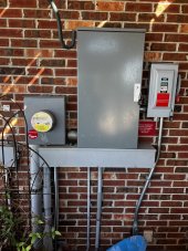
I think you might be overthinking it. I just went off the standard 2x15k and 3x15K wiring diagrams on pg 13-14 which shows the CTs installed upstream of the 200A main disconnect.Trevor,
Since I over think everything...
The manual states (pg 39) that CTs should be installed upstream of everything except for a Gen transfer switch, knife blade disconnect, etc. I've added (on paper) a separate PDB so that I could install the CTs downstream of the connection going to the knife blade disconnect. My drawing is attached. I'm not sure how your Solark will act if you throw the knife disconnect but maybe depends on settings. I was hoping to save money by only having 2 PDBs (or fewer Polaris lugs) after seeing your setup but to comply with the manual I might need 3. Not sure but I sure do appreciate this discussion.
Ray
By the way...if you're being inspected make sure your inspector won't shoot down the Polaris type lugs. As soon as my city inspector got out of the truck he said something to the effect of "there better not be any Polaris lugs."

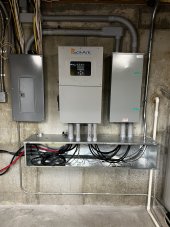
Also, what are you doing with the Neutral from the grid? She's gone man!
Yeah...that's a bit concerning. I mean between other inverter and the three conduit lines through the wall the trough is somewhat suspended but I'm not sure it'll be enough. I'll tackle that when I get to it. As slick as it looks right now I would have rather had a 12x12 hung off the wall with some decent air between the bottom of the inverters and the trough.Something to consider is inverter maintenance. If I'm seeing everything correctly, the trough is supported by both inverters. What would he need to do if one inverter needed removed? Temporarily support is from below? Add some big shelf brackets underneath?
EDIT: You guys want a laugh? Check out the attached. I might have overshot February's requirement. ??? Eh well...I'm gonna need every watt of that when it's 109-110F outside in mid-July.
Attachments
Last edited: