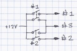
Diodes works best in this configuration, thanks. I am buying 3A diodes to put them through ~2A loads. Do they burn and cause fire in case the rated amperage is exceeded? Or do they just stop working?
Typically, diodes fail by shorting. Before shorting, they have a voltage drop of 0.7V or so. That is from the PN junction plus IR drop.
After shorting, would likely be lower voltage and somewhat reduced power dissipation, so would probably be cooler than the 150C or higher junction temperature which caused failure. But no guarantees how a failed part operates.
Do not assume that a "3A" diode could actually carry 3A, or that a "60V" diode could hold off 60V reverse voltage.
Specsmanship varies. As a minimum, specs mean this is the maximum instantaneous current it can carry, and the peak instantaneous voltage without causing immediate breakdown.
You need to analyze thermal situation. At both ambient temperature and if junction is at maximum allowed, what is the power dissipation of the diode at your maximum forward current, and at maximum reverse voltage?
Given datasheet specs and your thermal environment, would that power dissipation cause junction to sustain or rise above maximum allowed temperature? If so, it is overstress and will cause failure.
Some diodes are reasonably usable within their specs, if you provide the thermal environment described (e.g. a certain amount of copper PCB area.)
Others are not. You have to read the spec and analyze your design.
I would be more inclined to use a 10A or larger diode for 2A.