


You are using an out of date browser. It may not display this or other websites correctly.
You should upgrade or use an alternative browser.
You should upgrade or use an alternative browser.
4/0 battery cable in conduit?
- Thread starter faccnator
- Start date
timselectric
If I can do it, you can do it.
- Joined
- Feb 5, 2022
- Messages
- 19,076
Minimum conduit size for 2 - 4/0 is 1 1/2" .
dougbert
Solar Addict
here I have 2 4/0 cables inside of 1-1/2" for NEG
then another set of 2 inside of another 1-1/2" for POS
due to the nature of the connection and the strain relief, the 1-1/2 only bridges the gap between the raceway and the PDP box just over half way.
I then put a 2" conduit over the 1-1/2" with some cut slots on the bottom of the 2". When ready, slide the 2" up to cover the wire, and use a worm gear clamp to lock the 2" into place
is it code? do not know, but needed access to tighten the strain relief and the wire is protected for that short span
the other option was to NOT use any conduit, still use the upper strain relief and just a bushing on the bottom, leaving the 4/0 wire exposed

 diysolarforum.com

then another set of 2 inside of another 1-1/2" for POS
due to the nature of the connection and the strain relief, the 1-1/2 only bridges the gap between the raceway and the PDP box just over half way.
I then put a 2" conduit over the 1-1/2" with some cut slots on the bottom of the 2". When ready, slide the 2" up to cover the wire, and use a worm gear clamp to lock the 2" into place
is it code? do not know, but needed access to tighten the strain relief and the wire is protected for that short span
the other option was to NOT use any conduit, still use the upper strain relief and just a bushing on the bottom, leaving the 4/0 wire exposed
Solar house generator I started DIY back in 2000 - My path from Trace to Xantrex (on FLA battery) to XW Pro inverters on Tesla Model S batteries
I have no qualms about making neutral a loop, or ground a loop, so long as it doesn't offer a lower resistance path with insufficient ampacity. When current flows through L, I expect it to return through the closest N (or G in case of a fault), because that offers lowest inductive impedance...
diysolarforum.com
Last edited:
timselectric
If I can do it, you can do it.
- Joined
- Feb 5, 2022
- Messages
- 19,076
Nois it code?
But it works.
dougbert
Solar Addict
without the strain reliefs, the 4/0 cables would be hanging by their bolts on their respective bussesNo
But it works.
Yeah I see why you did that. Hanging there seems wrongwithout the strain reliefs, the 4/0 cables would be hanging by their bolts on their respective busses
dougbert
Solar Addict
Yeah I see why you did that. Hanging there seems wrong
I got the idea from david poz at this point of his video
robbob2112
Doing more research, mosty harmless
I got the idea from david poz at this point of his video
I've watched a number of his videos and they tend to make me shudder most of the time with things done that work but are not up to code and would fail any sort of inspection. Does it work? Yes, generally. Is some of it risky for heat/fire problems or other issues? YES.
In summary he scares me but then again a lot of the youtube guru types scare me with doing things wrong and presenting them as a good way to do something.
dougbert
Solar Addict
I've watched a number of his videos and they tend to make me shudder most of the time with things done that work but are not up to code and would fail any sort of inspection. Does it work? Yes, generally. Is some of it risky for heat/fire problems or other issues? YES.
In summary he scares me but then again a lot of the youtube guru types scare me with doing things wrong and presenting them as a good way to do something.
and his 4/0s just were exposed over to the the bus bar, yet were secure in the strain relief. Mine are in the 1-1/2" conduit then to the 6x6 raceway, protected and then exit behind a barrier where they attach to their bus bars
Last edited:
without the strain reliefs, the 4/0 cables would be hanging by their bolts on their respective busses
Is it the strain on the buses you’re worried about?
Any proper electrical crimped connector should be able to withstand way more force than gravity.
How do you think they crimp wire on the grid with 100’s of pounds of tension on them? Yes there is copper conductor on the system, not everything is aluminum or ASCR.
dougbert
Solar Addict
Is it the strain on the buses you’re worried about?
Any proper electrical crimped connector should be able to withstand way more force than gravity.
How do you think they crimp wire on the grid with 100’s of pounds of tension on them? Yes there is copper conductor on the system, not everything is aluminum or ASCR.
the NEG buss is okay, it is the POS plate that has a weak area
did you watch the video segment by David? it explains the possible issue - it is the BOLT of the hanging circuit breaker
He describes the 250 amp circuit breaker that has a bolt to which the POS plate is attached. To that plate the 2 4/0 cables are attached (hanging downward), which puts a straining load on that circuit breaker bolt.
Also attached to that plate are the 4 array POS input wires, though they don't have that much weight.
timselectric
If I can do it, you can do it.
- Joined
- Feb 5, 2022
- Messages
- 19,076
That plate seemed pretty sturdy when he torqued the connections to it.the NEG buss is okay, it is the POS plate that has a weak area
did you watch the video segment by David? it explains the possible issue - it is the BOLT of the hanging circuit breaker
He describes the 250 amp circuit breaker that has a bolt to which the POS plate is attached. To that plate the 2 4/0 cables are attached (hanging downward), which puts a straining load on that circuit breaker bolt.
Also attached to that plate are the 4 array POS input wires, though they don't have that much weight.
dougbert
Solar Addict
That plate seemed pretty sturdy when he torqued the connections to it.
yeah, it all would probably be fine without the strain reliefs
Last edited:
timselectric
If I can do it, you can do it.
- Joined
- Feb 5, 2022
- Messages
- 19,076
I'm not against strain relief. I use it every day.
I just think that particular concern was exaggerated.
I just think that particular concern was exaggerated.
I may not be looking correctly, but it looks like the 2 conduits with the red stickers are terminated at the inverter using metal terminal connectors to PVC conduit. If so, this is a NO-NO. Metal to metal, PVC to PVC. If this is the case, then unless those metal terminators are properly grounded, they would present a shock risk. Is the buss bar or battery enclosure grounded properly as well as the inverter? Is there a proper ground cable in those conduits?
Can I ask how large of a battery bank you have in input and output amps for charging and discharging?
I had a 900 amp bank and a single pair of 4/0 handled it without a problem because the inverter could never even come close to drawing anywhere that amount of power, even for starting a 5 HP electric motor.
dougbert
Solar Addict
ok, this discussion has me convinced to R&R the current conduits with full conduit on those battery cables, ie remove the strain reliefs
for better context here is AC side of my system followed by the inverters (well 1 inverter and space for the 2nd inverter) and MPPTs and battery


and the DIY battery, tesla modules, no battery case

currently I have 1400 amp-hrs of battery, 60kwh. On the path to 100kwh
The battery can discharge 350 amps and will charge at 240 amps when I complete filling all the arrays
The 2 inverters are limited to 14,400 watts of discharge due to internal 60 amp breakers. That would draw 288 amps, through 2 250amp breakers
It is Schneider (The manufacturer) who specified 1 4/0 cable set PER inverter, with a 250 amp breaker. I have 2 sets of 4/0 cable because I am preparing for the 2nd inverter
these pics came from page 1 of my build thread, link in signature
system schematics are on that page 1 as well
I chose the Schneider path some 5-6 years ago.
Today, I would go with the EG4 6000XP, probably with 4, maybe 5 units, and build the balance of system to have a future of 8 inverters - yeah with 200 amp service panels
for better context here is AC side of my system followed by the inverters (well 1 inverter and space for the 2nd inverter) and MPPTs and battery
and the DIY battery, tesla modules, no battery case
currently I have 1400 amp-hrs of battery, 60kwh. On the path to 100kwh
The battery can discharge 350 amps and will charge at 240 amps when I complete filling all the arrays
The 2 inverters are limited to 14,400 watts of discharge due to internal 60 amp breakers. That would draw 288 amps, through 2 250amp breakers
It is Schneider (The manufacturer) who specified 1 4/0 cable set PER inverter, with a 250 amp breaker. I have 2 sets of 4/0 cable because I am preparing for the 2nd inverter
these pics came from page 1 of my build thread, link in signature
system schematics are on that page 1 as well
I chose the Schneider path some 5-6 years ago.
Today, I would go with the EG4 6000XP, probably with 4, maybe 5 units, and build the balance of system to have a future of 8 inverters - yeah with 200 amp service panels
Last edited:
I used to watch his videos but eventually couldnt stand them. Nothing necessarily wrong just, something about them I could t stand.the NEG buss is okay, it is the POS plate that has a weak area
did you watch the video segment by David? it explains the possible issue - it is the BOLT of the hanging circuit breaker
He describes the 250 amp circuit breaker that has a bolt to which the POS plate is attached. To that plate the 2 4/0 cables are attached (hanging downward), which puts a straining load on that circuit breaker bolt.
Also attached to that plate are the 4 array POS input wires, though they don't have that much weight.
After watching the clip I still stand by my thoughts, excess for excess standpoint, to each his own.
This advice is free and is based on my experience receiving electrical contracting and performing electrical work on my projects.
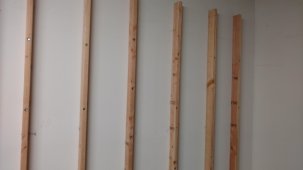
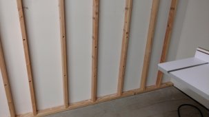
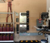
The installation is not "clean". Here are a couple of suggestions for people planning installs. These photos were taking during an install in 2017. There are more choices now and different materials since then, but they are an example of doing some planning of your equipment layout rather than just sticking things up on the wall. And re-doing/adding to a system is always twice as difficult if not even more.
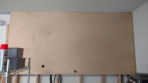
If you have a wall covered by drywall, it is possible to use lag bolts and attach 2 x 4's to the drywall studs. This adds depth needed to run wires in and out of conduits. Then, using a 4 x 8 panel such as 5/8 to 3/4" plywood, lay the panels flat. Mark on the panel the location of the studs. Then place down your hardware creating a layout that looks neat. Trace these outlines with a pencil. Now, on the panel mark where wiring and conduits will come through the plywood from the back of the panel such as into wireways. Mark on the studs where you need to drill through to run wires across the studs, mount outlet boxes, etc before attaching the panel with the tracings and holes cutouts to the wall. Position the panel on the wall and attach. Do this with as many panels as is needed. Run you wiring in the 2x4 spaces BEFORE YOU ATTACH THE PANELS and as you attach them, pull the wiring through the panel holes you made. Your finished look will be very clean. If you want a simple finish on your panel, just put on 2 coats of wipe on shellac with wax which dries in 10 minutes.
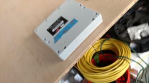
Secondly, my advice is to understand the use of PVC and metallic boxes when doing electrical work. PVC must be used outdoors to help prevent electric shock in case of wire shorts or ARCs and for inground burials. Electric metallic boxes such as panels, breaker switches, disconnects installed outdoors need to be outdoor rated such as NEMA 3R. When outdoors and a PVC conduit is connected to a metallic box, there always must be a proper ground connection of the metallic box using a ground wire coming from inside the conduit.
Indoors, metallic conduit, rigid or flexible connects to metallic boxes. PVC connects to PVC. Metallic to metallic proper connections carry the ground potential within themselves to prevent electrocution. When you try to join an metal fitting to a PVC box or a PVC conduit to a metallic box, that ground connection is lost. Now, items such as metallic cabinets with batteries inside must all have a ground wire, including the batteries and metallic conduit should be used to connect them. The ground wire is necessary in case the batteries and the painted surfaces break a proper ground connection. Metallic conduit and boxes are not painted.
In the images above, there are multiple joints that do not follow the PVC to PVC and metal to metal requirements.
The installation is not "clean". Here are a couple of suggestions for people planning installs. These photos were taking during an install in 2017. There are more choices now and different materials since then, but they are an example of doing some planning of your equipment layout rather than just sticking things up on the wall. And re-doing/adding to a system is always twice as difficult if not even more.
If you have a wall covered by drywall, it is possible to use lag bolts and attach 2 x 4's to the drywall studs. This adds depth needed to run wires in and out of conduits. Then, using a 4 x 8 panel such as 5/8 to 3/4" plywood, lay the panels flat. Mark on the panel the location of the studs. Then place down your hardware creating a layout that looks neat. Trace these outlines with a pencil. Now, on the panel mark where wiring and conduits will come through the plywood from the back of the panel such as into wireways. Mark on the studs where you need to drill through to run wires across the studs, mount outlet boxes, etc before attaching the panel with the tracings and holes cutouts to the wall. Position the panel on the wall and attach. Do this with as many panels as is needed. Run you wiring in the 2x4 spaces BEFORE YOU ATTACH THE PANELS and as you attach them, pull the wiring through the panel holes you made. Your finished look will be very clean. If you want a simple finish on your panel, just put on 2 coats of wipe on shellac with wax which dries in 10 minutes.
Secondly, my advice is to understand the use of PVC and metallic boxes when doing electrical work. PVC must be used outdoors to help prevent electric shock in case of wire shorts or ARCs and for inground burials. Electric metallic boxes such as panels, breaker switches, disconnects installed outdoors need to be outdoor rated such as NEMA 3R. When outdoors and a PVC conduit is connected to a metallic box, there always must be a proper ground connection of the metallic box using a ground wire coming from inside the conduit.
Indoors, metallic conduit, rigid or flexible connects to metallic boxes. PVC connects to PVC. Metallic to metallic proper connections carry the ground potential within themselves to prevent electrocution. When you try to join an metal fitting to a PVC box or a PVC conduit to a metallic box, that ground connection is lost. Now, items such as metallic cabinets with batteries inside must all have a ground wire, including the batteries and metallic conduit should be used to connect them. The ground wire is necessary in case the batteries and the painted surfaces break a proper ground connection. Metallic conduit and boxes are not painted.
In the images above, there are multiple joints that do not follow the PVC to PVC and metal to metal requirements.
Attachments
Similar threads
- Replies
- 2
- Views
- 227
- Replies
- 0
- Views
- 97
- Replies
- 67
- Views
- 5K