diy solar

diy solar

Solar house generator I started DIY back in 2000 - My path from Trace to Xantrex (on FLA battery) to XW Pro inverters on Tesla Model S batteries

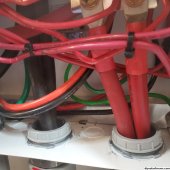
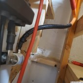
Inserting the new 4/0 cable into the NEG conduit

20230923_124632.jpg

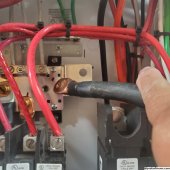
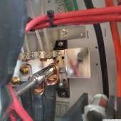
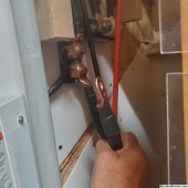
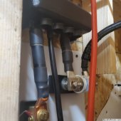
need to connect it that open contact point on the NEG bus

20230923_124902.jpg

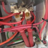
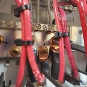
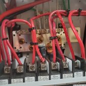
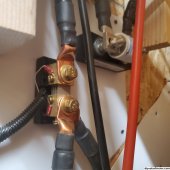
here is the POS dual 4/0 connection point on the 250 amp breaker buss

20230923_124907.jpg

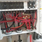
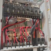
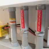
here is the lower DC portion of the PDP box with the DC array breakers at the top, and the inverter 250 amp breakers at top right - some ask do you really need the PDP? - well without it, one has to come up with another solution to contain what is in these pictures


20230923_124911.jpg


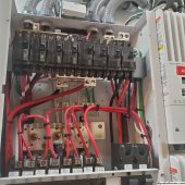
Here is the upper portion of the PDP box, AC is in the top half of the pic, and DC in the lower half of the pic

the DC NEG buss can been seen on the lower back wall where the new 4/0 will be mounted at


20230923_124913.jpg

Feeding the 2 4/0 cables into the strain relief glan - kudos to David Poz for finding and showing these in his YT video

20230923_125317.jpg

his video


20230923_125319.jpg
 
Last edited:
Tightening the cables onto the NEG bus

20230923_125733.jpg

the DC bus and the POS bus support 3 XW Pros by default. More XW Pros require external mounting busses and breakers (Well on the 60 amp MPPT CC's can have their breakers inside the PDP, the 80 and 100 amp MPPT CC's also require external breakers). The PDP is not rated for 600 VDC

20230923_125737.jpg

20230923_125739.jpg

both NEG and POS dual 4/0

20230923_130133.jpg

done connecting cables inside the PDP

20230923_130139.jpg
 
Last edited:
Now connecting the other end of the NEG 4/0 cable to the 500 amp shunt stud

20230923_130649.jpg

20230923_130914.jpg

need to construct 2 short segments for these to double them up as well
Main DC buss bars are rated at 600 amps, fuse is 400 amps


20230923_130917.jpg

and here is the last segment from the fuse back to the battery - 2/0 cable. That is what came with the Jack-In-The-Box.

20230923_130928.jpg

One thing I could to is to cut/shorten the 2/0 legs and replace with 4/0 segments, thus reducing the length of 2/0 that carries the amperes.
Such a task would not replace the 2/0 that enters the box, just shorten them outside the box

Jack Rikard did indicate they tested the 2/0 wire, in developing the Jack-In-The-Box, to 330+ amps. He did mumble the cables were "warm"

In this configuration, 2 XW Pros, can only support 14.4 kw MAX (due to internal 60amp relays), which would be DC 288 amps from the battery (shared across the 2 inverters, each with a 250 amp breaker)
 
Last edited:
Power back on time

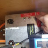
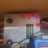
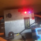
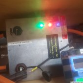
Turning Jack-In-The-Box back on, and waiting for the surge resistor to pre-charge the inverter

BLUE light power on
RED light pre-charge stage
GREEN light contactors indicate full connection reached, about 15 seconds total time (Programable)

20230923_131020.jpg

20230923_131026.jpg

20230923_131054.jpg

20230923_131103.jpg

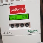
turn on arrays' breakers

20230923_131734.jpg

battery conduits buttoned up

20230923_131741.jpg

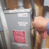
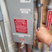
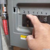
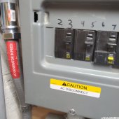
switch from GRID power to SOLAR/BATTERY power

20230923_131756.jpg

20230923_124339.jpg

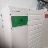
Inverter back to normal state of running the house

20230923_131803.jpg

turning off the GRID breakers

20230923_131830.jpg
 
continuing my generator adventure

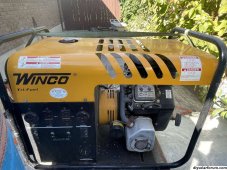
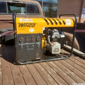
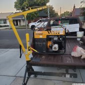
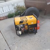
I scan the local classifieds for cheap/broken generators and I found one. A Winco TF9000E/Q 8000 watt continuous/9000 watt surge generator with a B&S Vanguard V2 16HP engine. Engine works great, but seller said one day the power head didn't make any more power. Used at his cabin to power the place, pump water etc. He had had it for many years and kept it clean

So he did not want to debug it, bought another gen-set and was selling this for $50 (Winco generators can sell for $1000 to $4000)
Tri-fuel from the factory

Winco gen.JPG


I quickly contacted him and said I wanted to buy it.

Got it on my truck and took it home. Bought a dolly at Harbor freight for $37 so I can wheel it around


power center near exhaust.jpg

used my receiver cherry picker to get it off the truck

20230926_191557.jpg

20230926_192050.jpg


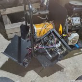
opened it up and used a VOM to measure things and check things out, all looked good.

wiring opened up.jpg

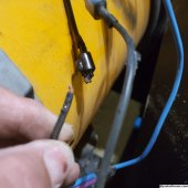
and then I found the issue. Here is what I found at Fault

Holding fried CAP lead.jpg
One of the 2 wires that connects to the 3 capacitors (40uFds each) in parallel. It had rubbed against a frame, worn off the insulation, shorted and melted the wire

So I fixed the wire, put things back together and fired it up (on propane, it has never had gasoline in it - BTW built in 1997) and WE HAD POWER

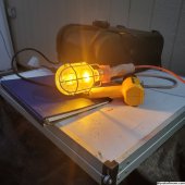
Amber light bulb

20231006_190819.jpg

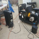
So I loaded it up with loads to see how it was performing

20231013_175245.jpg
 
Last edited:
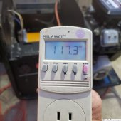
with no LOAD voltage was 117v, and as I added loads to 3000 watt voltage dropped to 107

20231006_190904.jpg

replaced the 25 year old caps with 3 new ones (took 10 days to arrive) and voltage raised 2-3 volts to 120v with no load

at 3000 watts voltage was 112v

James Condon (Youtube generator fixer) indicated this unit has had low voltage issues over time. No AVR and brushless

Still I can use it to feed the chargeverter to charge the batteries just fine

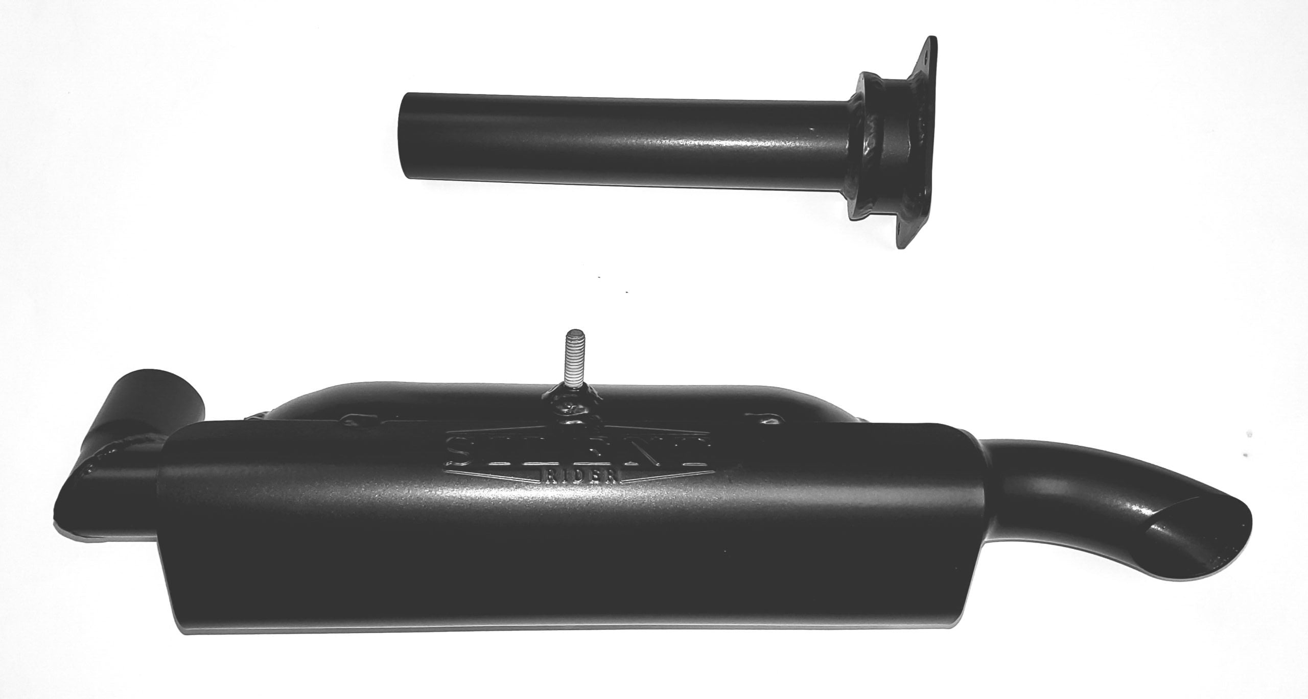
today I added a good muffler and the exhaust noise dropped 10db


with new muffler.jpg

So I say: Good find for backup power to my backup power. Will extend Natural Gas line to generator location. Also have hoses for propane as well. Do not want to put gasoline in it


So $50 initial, then $132 for the caps. Finally new air filter, oil filter, spark plugs, 2 valve cover gaskets (valves needed adjusting).

I am still awed by this "gift"
 
Last edited:
Wow, just, wow...

$50! I think that is fantastic.

Odd it can't keep up at 3000W though.
Is it all on one leg?
 
The Harbor Freight plastic dolly is fragile. I put a load binder strap around it to secure something, and the sideways force cracked the plastic side.

Looks like you've got a bolt through. Consider reinforcing and spreading load around the bolt by filling with epoxy or epoxying in a thicker piece on the bottom. Also look at how sheet metal frame has edges bearing on a small area.


Decades ago when I could buy an automotive muffler for $20 at Grand Auto, I put on on my Onan welder/generator. Much quieter.
 
Last edited:
Wow, just, wow...

$50! I think that is fantastic.

Odd it can't keep up at 3000W though.
Is it all on one leg?

here is part of my conversation with Jim

MINE:

On the Winco brushless, 8000 watts (gasoline), I have installed the 3 new capacitors and it did improve voltage about 2 volts AC across the load range tests

this is on propane, new CAPs. I did bump Hz to 62.5

NO Load: 120.3v @ 62.5
1400w: 115.1v @ 61.3
2580w: 111.7v @ 60
3160w: 109.7v @ 59.5
3830w: 109.2v @ 59.5
4380w: 107.7 @ 59.2

would like to see what 5000w or maybe 6000w will do, but my 15amp breakers tripped.
need a break out box for the 50a receptacle

I will being using this generator to charge my solar batteries and not directly power the house. The charger can still use the lower voltage to convert to 48vdc

HIS Response:

A generator like that, you will see on average a 20 volt sag from no load to full load. So the drop you are seeing is normal. The big issue is the no load voltage. It should be starting closer to 130 volts. I did a quick search on your model and found others complaining about the same. No load voltage at around 120v and then it drops as the load is increased. 62.5 hertz is about the limit you should go to on the engine speed. The only other option would be to try capacitors with a different uf rating. Of course it would be trial and error probably not worth the cost.

--Jim

Trying different values of capacitors would be interesting, BUT I don't know which direction to go: Larger uFs? Lower? an how much? 10uFds? 5?

at $132 per set that is costly

I have learned much from his videos

 
Last edited:
The Harbor Freight plastic dolly is fragile. I put a load binder strap around it to secure something, and the sideways force cracked the plastic side.

Looks like you've got a bolt through. Consider reinforcing and spreading load around the bolt by filling with epoxy or epoxying in a thicker piece on the bottom. Also look at how sheet metal frame has edges bearing on a small area.


Decades ago when I could buy an automotive muffler for $20 and Grand Auto, I put on on my Onan welder/generator. Much quieter.

I understand. The official 2 wheel kit is $230 from Winco - geez
 
Trying different values of capacitors would be interesting, BUT I don't know which direction to go: Larger uFs? Lower? an how much? 10uFds? 5?

at $132 per set that is costly

Have the old caps? What value due they read?
Could place in parallel for greater capacitance.

New caps increased voltage slightly? Probably new caps had more capacitance?

I would have thought there was an exciter winding fed by something like an adjustable resistor.
 
How quiet is it after the gensilencer install? I need something for my 12kw generator. It's WAY to loud.
 
Another guy used a large air tank as muffler, said it was extremely quiet.
My civic has "resonator" chambers in plastic box on intake, quieting another source of noise.

I'd want to capture waste heat. Maybe coil of water tube inside secondary muffler.
 
How quiet is it after the gensilencer install? I need something for my 12kw generator. It's WAY to loud.

a lot

the loudest noise now are the sounds from within the generator proper

I like how much quieter the exhaust is. working on a shed with sound dampening material now to soak up the other sounds
 
Have the old caps? What value due they read?
Could place in parallel for greater capacitance.

New caps increased voltage slightly? Probably new caps had more capacitance?

I would have thought there was an exciter winding fed by something like an adjustable resistor.

they are 39, 39 and 40uFds well within the +/- 6% (40 is what they are rated at)
yet they are 25 years old and the new ones DID HELP by 2-3v

I need to learn what are the principles that being used here, software guy here with barely passing EE knowledge in that stuff

UPDATE

later I post I upgraded to 50uFD caps and brought the voltage up to 127v or so NOLOAD and 114v at 5000w

 
Last edited:
Xc = 1/(2 pi f C)
Ic = -j V/Xc

Ir = V/R

|I| = sqrt(Ic^2 + Ir^2) ... Pythagorean theorem for series RC circuit; imaginary numbers are orthogonal to real.
Angle, use trig.

I'm not sure what the capacitors are used for, where they are in the circuit. Resonator with "L" of windings? Frequency dependent current into excitor winding? Does this generator have brushes for rotating exciter windings, and stator windings deliver AC?

Rtotal = R1 + R2 ... series circuit
Rtotal = 1/(1/R1 + 1/R2) ... parallel circuit

Ctotal = C1 + C2 ... parallel circuit
Ctotal = 1/(1/C1 + 1/C2) ... series circuit

Power dissipation of resistors, voltage applied to capacitors, and ripple current handling of capacitors must be considered if individual ratings are too low (not a problem in this case.)

Inductors have similar math to capacitors, but go in numerator rather than denominator, so don't get the negative sign for "j" (1/j = -j)

Things involving sine waves are so much easier in analog than in software. Can be done in software, but requires extensive libraries or code for Fourier and Laplace. But magnitudes and angles can be done long hand or on graph paper. Smith chart, too.

Most of the math you wouldn't mess with tweaking a generator. maybe to understand the circuits. For resistor in series with an inductor, I found the orthogonal vector math convenient to calculate current.

I'm EECS, but software has passed over my head like a tsunami. I hunt and peck doing sequential commands in Matlab for the most part. Photon transfer curve of image sensors, BH curve of inductors, instrument control.

[Edit: corrected above to use w = 2 pi f, not just f. Radians, not Hz.]
 
Last edited:
here is the only wiring diagram I have found so far

L1, L2 and Neutral at the bottom, coming out of the stator
2 #14 wires come out of the power head, being the excitation winding, and connect to the caps, as shown in the upper left

this is a brushless generator

on the right is the wiring of the power panel, fed by L1, L2 and Neutral windings

wiring diagram 2.png
without the caps, no power since the excitation winding is not energized - as shown when the one lead had shorted out

on the right is the view the back side of the receptacles:

upper right is a 120v NEMA 5-50r with a 45 amp breaker
upper left is a 240v NEMA 6-50r with a 35 amp breaker
upper middle two are NEMA 5-15r with a 15 amp outlet each
lower left is a 120/240v SS2-50r (Shore power designated receptacle which is a different form of NEMA L14-50r or CS6364C). One leg is 45 amp while other leg is 35 amp breaker, weird

For NEMA designations see https://www.iqsdirectory.com/articles/power-cord/nema-connector.html
 
Last edited:
3 caps in parallel. You can try 2, and you can try 4 using an old one.

No details on what's inside the generator black box.
 
3 caps in parallel. You can try 2, and you can try 4 using an old one.

interesting

No details on what's inside the generator black box.

which black box?


HERE is the power head open, where I measured Ohms in the windings

on the end of the rotor, are 2 diodes

L1, L2 and neutral are all 10 awg with BLACK insulation
before separating them, I marked them white for neutral and red for L2, left L1 black

labeld Neutral and RED Legs before disconnecting.jpg,
 
Last edited:
"Black box" meaning a picture of the round generator but no details.

Brushless you said. Although not permanent magnet, it has rotor windings. I suppose there is something that induces current into it.

I don't understand how it works, but appears resonance with the caps determines current induced in rotor windings.
Why it is still running several volts low no-load, I don't know. I expected something like a potentiometer, but I haven't messed with generators much.
 
Some posting from smokstack https://www.smokstak.com/forum/threads/brushless-alternator-with-capacitor.16338/

Re: Brushless Alternator principles

As I understand it the capacitor introduces a phase shift between its associated stationary winding and the rotating "field" (rotor) winding to induce an alternating current that is rectified by the mentioned diodes in the field winding.

The rectified field current produces usable output voltage in the "load" stator windings and there you go.

Capacitor excited sets generally have poor V regulation as compared to sets with electronic regulation. The advantage is cost and not much to go wrong. Some industrial cap excited sets are "self current limiting" in that you can short the load output and the Voltage/current will drop to a level that will not "instantly" damage the sets windings. They are common on light carts and such.

Sometimes you can get more V by increasing the capacitor value. If the set is old, check the cap value before you do anything else. If you elect to change value be careful, as too much C will cause V to soar on no /light load and some loads that look capacitive to the set.

Re: Brushless Alternator principles

The capacitor is a common method of voltage regulation on smaller, less expensive generators. Coleman and many others use them - it's a common method on European generator ends. The capacitor stores a charge which balances a winding at an output voltage (say 120 volts). If the output voltage goes down, power flows from the capacitor increasing excitation, and if the voltage goes high, the capacitor stores excitation, causing the voltage to drop until they are in balance again. Very simple system, no brushes to wear out, no expensive voltage regulator needed. Works well. If the voltage is too high or low, check the capacitor. If it is rated at 25 microfarads, check it against a multimeter that can check capacitors. If the capacitor is within 2 or 3 uF of rating, it's ok. You can vary the output voltage by changing the capacitor. Try a 30 microfarad instead of a 25 and see how the voltage changes. It varies from generator end to generator end, but it may give you the boost you're looking for in output voltage.

Re: Brushless Alternator principles

Replace cap. with a new one. If the voltage is still low you can add caps in parallel to increase the value.

Kent

Re: Brushless Alternator principles

Well, two surprises: First, this thing has great voltage regulation. With the stock 25 uF cap, the no-load voltage was 111 V and it dropped to 110 V at a full 3 kW load.

The second surprise was that it takes a large change in capacitor value to increase the output voltage. With 40 uF, I get 120 V at no-load and 118 V at full load. All voltages are RMS, and I adjusted the governor as I changed the load to keep the frequency at 60 Hz.

I also experimented with adding a capacitive load to the main output, and it was stable - in fact, the output voltage dropped as I added capacitance there.

So, there must be some some drawback to this simple 'capacitor regulation' scheme, but I haven't seen it yet...


Re: Brushless Alternator principles

It sounds as if Kubota did their homework on the winding ratios in your set. As you found, the cap value isn't too critical in a "good" set within a reasonable range. Problems usually only show up when a certain critical cap value is exceeded.

Also in the case of a non-linear load such as a switching power supply,(if you run your computer off of one) plug an incandesent lamp or two in as well. I don't know that it would hurt anything, but the waveform looks "slanted" on a 'scope when only a switching-type load is applied.

The only troubles I have had with the several old Cap regulated sets I have owned are bearing issues and the cap going "open".
 

diy solar

diy solar
Back
Top