And it is live!
I followed the commissioning procedure step by step. Disconnected AC side, connected DC side, and LAN cable. Connected the battery and the battery CAN cable. Started the DC side, go through the wizard, and finally click save. Then connected the AC breaker and ... nothing. The unit was up, but it was not generating any power. It was waiting for some permission.
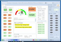
Took me around 45 minutes to find out what was going on. Almost got a bold place on my head from scratching it. And finally, I clicked the "AC ON" button on the front panel. Something clicked and I heard buzzing noise. Grid - 2W, inverter 1kW.
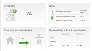
The BMS CAN wiring was almost straightforward. Almost because the SMA folks are counting the RJ pin numbers on the socket, not on the plug. This leads to a pin mismatch and I managed to swap the CAN L and CAN H lines. Looked at the manual again and said - nope, no way the Seplos folks could have reversed the order of the pins. But swapped the CAN L and CAN H wires and suddenly the inverter showed 45% SOC for the battery.
The heat insulation sheets around the battery should keep it at >= 15C. There is a metal stand on the wall that should withstand the load. It was a decent challenge to put the battery up there. Ignore the fridge below
")
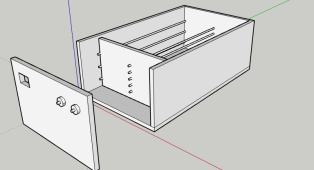
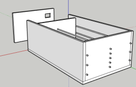
. And the AC box - I just patched a connection point there and most of it will be rebuilt in the summer.