Hedges
I See Electromagnetic Fields!
- Joined
- Mar 28, 2020
- Messages
- 21,201
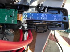
Your earlier meter photos showed near full Imp current. But you had well below Vmp voltage. That is highly suspicious.
Even if you thought sky was clear, you can't know without instruments. But 10.47A reading vs. 10.96 Imp says it was a cool, clear sunny day.
Not unless it is a bug. The inverter would draw voltage down low to search for higher wattage peaks, but only briefly. It would dwell in vicinity of highest peak.
My WAG is that previous connection to 120V caused inverter to set about 2500W maximum (due to max current through transistors driving AC). But I would have expected it to curtail wattage with higher voltage, reduced current. Not lower voltage.
I don't suppose you have any way to read and possibly set parameters? (Which you just did, later post shows normal wattage) SB can probably talk by Ethernet, possibly WiFi unless built during the chip shortage. If we do find something screwy, given internet connection SMA support might be able to reach in and fix it.
It seems clear (or most likely assuming my Wild @$$ Guess is incorrect) that either there is voltage drop (and power dissipation) somewhere along the circuit path, or else some panels (or RSD) are letting current bypass them without delivering any themselves. I think a part shaded panel would then deliver its (shaded) Isc, probably in parallel with diode bypassing balance of current.
Them newfangled RSD boxes would be my preferred guess.
If you had access to IR camera, you might spot the outlier panel.
If those were optimizers you could probably read parameters per panel.
You could bypass optimizers one at a time, or do a binary search (half at a time.) Disconnecting half the optimizers would be more work than one at a time. Jumper to bypass half the array would just be one wire. I think MPPT will operate down to 100V so half probably works, but can't repeat binary search with half of a half. At least the middle row of panels isn't convenient to reach and rewire. Do shut off by opening AC breaker, then DC disconnect, before messing with DC wiring!
"[US] Country Set UL1741/2016/120"
I thought "120" was odd, but that's just L-N voltage. manual says,
"240 V split-phase system L1, L2 and N • UL1741/2016/120 L-N-L"
Even if you thought sky was clear, you can't know without instruments. But 10.47A reading vs. 10.96 Imp says it was a cool, clear sunny day.
So possibly, this is a behavior from the inverter I am not a subject matter expert at this, so I don’t know if my conclusion is accurate
Not unless it is a bug. The inverter would draw voltage down low to search for higher wattage peaks, but only briefly. It would dwell in vicinity of highest peak.
My WAG is that previous connection to 120V caused inverter to set about 2500W maximum (due to max current through transistors driving AC). But I would have expected it to curtail wattage with higher voltage, reduced current. Not lower voltage.
I don't suppose you have any way to read and possibly set parameters? (Which you just did, later post shows normal wattage) SB can probably talk by Ethernet, possibly WiFi unless built during the chip shortage. If we do find something screwy, given internet connection SMA support might be able to reach in and fix it.
It seems clear (or most likely assuming my Wild @$$ Guess is incorrect) that either there is voltage drop (and power dissipation) somewhere along the circuit path, or else some panels (or RSD) are letting current bypass them without delivering any themselves. I think a part shaded panel would then deliver its (shaded) Isc, probably in parallel with diode bypassing balance of current.
Them newfangled RSD boxes would be my preferred guess.
If you had access to IR camera, you might spot the outlier panel.
If those were optimizers you could probably read parameters per panel.
You could bypass optimizers one at a time, or do a binary search (half at a time.) Disconnecting half the optimizers would be more work than one at a time. Jumper to bypass half the array would just be one wire. I think MPPT will operate down to 100V so half probably works, but can't repeat binary search with half of a half. At least the middle row of panels isn't convenient to reach and rewire. Do shut off by opening AC breaker, then DC disconnect, before messing with DC wiring!
Inverter parameters:
"[US] Country Set UL1741/2016/120"
I thought "120" was odd, but that's just L-N voltage. manual says,
"240 V split-phase system L1, L2 and N • UL1741/2016/120 L-N-L"