diy solar

diy solar

60mv Voltage deviation one cell

Roeltwee

New Member
Joined
Feb 27, 2022
Messages
8
Hello Members,

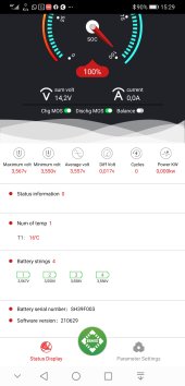
I bought 4 eve lf230 cells from docan power and did a top balance. When the charger connected Al the cells where 3.652 or 3.653. Then connected them in series and only one cell has 60 mv deviation. The other cells are within 5mv difference is this a problem. Maybe add an active balancer? Or maybe I did something wrong. I hope you can help me!


Screenshot_20220511_212235_com.inuker.bluetooth.daliy.jpg
 
Near the top and near the bottom of the battery cell voltage range, a little change in state of charge makes a lot of voltage difference. If you discharge the battery just a little, you will normally see the voltages settle closer together. Also, when you remove the charger from LiFePo4, they will naturally settle to a lower voltage, something around 3.40v to 3.45v as I recall.
 
So from the picture you show one cell is higher than the others, it’ll prob bleed down after a little more time has past.

I’d run a few load cycles and keep any eye on it. When charging you’ll probably notice this cell will differ the others, but if only .06v delta at the top end of charge is nothing to worry about.
 
Oke thanks for the tips. Maybe I will charge a couple times to 14.6 next week. I hope the balance current of the daly bms is enough.
 
I would suggest to only charge to 14.2v ( 3.55v / cell ). You gain very little capacity over this voltage. Cycle the pack a few times and observe. Do not expect too much from the Daly BMS balancing. You can always add a Heltec 5amp balancer in the future. I keep mine connected permanently ( against the advice of some ) and have had no issues.
 
Last edited:
Check your connections. Clean all contact surfaces and ensure the fasteners are tightened to the proper torque. Don't over-torque! Also, ensure that the cell terminals are all on a parallel plane. If they aren't then the bus bars may not be making good contact.
 
Connections everything I checked. The first cell is off Bij 60 to 90mv .I think I am gonna add an active balancer. Only use it at high SOC. Any suggestions for an active balancer? The heltec 5a is that a good one?
 
I agree. If you put the tiniest of loads on there FIRST.
Run it down TO 98% and see what the deviation is then.
You are overreacting getting an active balancer quite yet
 
This chemistry is new to me currently my deviation is 1mv at 97% state of charge with no loads on it.
 
Connections everything I checked. The first cell is off Bij 60 to 90mv .I think I am gonna add an active balancer. Only use it at high SOC. Any suggestions for an active balancer? The heltec 5a is that a good one?

The Heltec 5a active balancer is used in my system with two grade B 271ah 8s 24 VDC Lifepo4 battery banks and it works well.

For 4s 12VDC Lifepo4:
For 8s 24VDC:

There are (run) solder pads on the Heltec active balancer that can be used to turn the balancer on and off with a switch.

My system uses the relay on the Victron Energy BMV 712 battery shunt display wired to the run solder pads to switch on and off the Heltec active balancer.

At voltages above 27.3VDC the Heltec active balancer is switched on and balancing begins. As the voltage continues to increase above 27.3VDC the Solar Charge Controllers in the system are programmed to go into Boost (absorb) charge at 28 to 28.2VDC for 10 minutes. During boost charge mode the Heltec active balancer keeps all cell voltages at less than 3.55VDC as the cells balance. At the end of 10 minutes of boost charge mode all cells are within 30 mv or less. After 10 minutes of boost the SCC's are programmed to go into float mode at 27.4VDC. The cells continue to balance and after a few minutes in float the cells are within 15 mv or less. The SCC's stay in float mode while suppling loads during the day. Toward the end of the day (or if clouds build) when SCC's cannot hold float and the battery voltage goes below 27.2 the active balancer is turned off by the Victron shunt relay.

Originally the Heltec active balancer was just wired to the cells and it ran all the time, but I found that cells would balance mid charge and when the voltage approached the boost voltage at high current charge, some of the cells would trigger the BMS cell voltage limit (3.65 VDC) and shut down the battery bank. During mid charge of the battery banks some of the cells can vary 30mv or more and the Heltec balancer would balance the cells at mid voltage throwing off my top balance. I guess that's due to grade B poorly matched cells. Once the Heltec active balance was triggered to only balance at 27.3 VDC and above everything worked fine.

Due to the load demands on my off grid solar system it may be weeks before the system is able to charge up to Boost (absorb) charge level of 28 to 28.2VDC depending on sunny vs cloudy days in my area. Even with that amount of time in-between boost (full charge) the cells still balance well with the Heltec 5a active balancer. Without the Heltec active balancer one or more of the battery bank cell(s) was prone to over voltage triggering a BMS disconnect on that battery bank.

With my two Overkill Solar 8s BMS set at 3.65 Cell Voltage Limit this works well for both battery banks that are in parallel configuration.

It is my understanding that a Digital low voltage battery cut-off relay module is able to turn on and off the Heltec active balancer like the Victron shunt relay, but I have not tried it since my system has the Victron BMV 712 shunt. If some tries this battery cut-off relay module please post your results here.
 

Attachments

  • 5A active balancer manual-Heltec.pdf
    1.6 MB · Views: 2
Last edited:
Have you confirmed the voltages at the cell terminals with a meter?
At the high state of charge the delta you have is not excessive and nothing to worry about.
 
When cells are fully charged above 3.5v and charge current is tapered down to low level there will be surface charge build up that creates the no load cell voltage above 3.45v, which is full charge no load rested voltage for LFP cells.

This surface charge has very little energy storage with a maximum equivalent of about 0.01% of capacity rating of battery. You can bleed it off with about 1 amp load for about a minute, after which in a few minutes of no load resting, cell will settle to about 3.45v.

If you leave cells unloaded after full charge, this surface charge will bleed off on its own but can take a few hours to a couple of days. The rate it bleeds down is dependent on individual cell and does not relate to cell capacity or balance.

If there is no surface charge and rested no load voltage is above 3.45v per cell, the cell is fully charged.

There is overpotential voltage bump during charging and slump during discharge delta from no-load rested cell voltage. The overpotential terminal voltage bump for charging or slump during discharging is energy overhead required to move lithium ions within cell. It's bump or slump voltage delta from rested no load cell voltage depends on demanded cell current, cell temperature, and cell condition.

When charging above 3.5v, as cell becomes fully charged, the constant applied charger absorb voltage causes the drop in overpotential required to support tapering charge current to be traded for surface charge build up in cell layers, mostly negative anode graphite layer. It is like a supercap. This creates the cell voltage greater than inherent 3.43v LiFePO4 full charge cell potential.
 
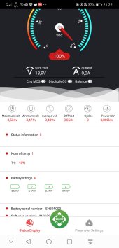
A week ago I solved the problem I installed a capacitive active balancer. De soldered the run contact and I am planning to do a manual balance every 2 weeks. Currently charging to 3.45 volt per cell. The delta is now perfect! On the screenshot i charged up to 3.55 volts per cell and the deviation is 17 mv. Half an our later the cells are within 5mv deviation! In the future I want a JK bms because they have a good balancing function and just have one BMS instead of an extra seperate balancer... Screenshot_20220521_152949_com.inuker.bluetooth.daliy.jpg
 
I had exactly the same issue with some 60Ah Winston cells. I have 27 of these that are now about four years old, and added three more that are brand new. I connected all thirty in parallel and charged them up to 3.65 volts, and then let them sit for 24 hours still all connected in parallel with nothing else connected.

Over the 24 hours the voltage fell back to 3.60 volts which is o/k.

Then I connected them back all in series, and found that at the normal average charging voltage of 3.45v the three new cells were pretty much the same, but sitting about 50mV higher than the other 27 which were also all pretty much the same.

So I suggest that balancing at 3.65 volts might not be the ideal solution, but balance at the normal maximum charging voltage will give much better overall cell to cell voltage tracking.
 
Back
Top