diy solar

diy solar

99.5% Efficient Inverter Design

I read through the instructible and here are my thoughts:
  • It is not really practical for the typical home DIY, I would add more solar panels rather than add the complexity and complications of this design to get that ~5% to ~10% extra power.
  • However, it is a very clever design. I like the out-of-box thinking. This type of out-of-box thinking is where the breakthrough changes in technology come from.
  • As @BiduleOhm points out, there are similarities between this and some of the new solid state inverters that are coming out.
  • At this point, it is more a proof of concept. There seem to be a lot of tweaks that would need to go into a final product.
  • An interesting aspect of the concept is that you can use SW to make substantial changes to the frequency, voltage and wave-form of the output.
  • It requires a separate charge controller for each battery bank. (This does not demand, but certainly implies a separate solar array for each bank. It would take a special charger design to use the same array for all 3 banks)
  • Special care must be taken to balance match capacity of each battery bank to the needs. (And the associated chargers and Solar arrays for each bank)
  • Some of the gains of the design are probably going to be lost in the extra chargers and potential over-paneling on one or two of the banks.
  • It might be a good concept for a grid scale storage system where getting that last bit of efficiency is important and the batteries, chargers and arrays are can be tuned/designed to optimize for the concept.
  • There is nothing inherently unsafe in the concept but care would need to be taken to ensure the design of the concept is safe.
  • It does not use magnetics/transformers in the power conversion but:
    • The instructible does discuss putting an inductor on the AC Output to limit surge current. (It did not sound like that has been
      done in the prototype.)
    • I suspect the small transformer shown in the picture is for creating power for the control electronics.....but that is a guess on my part.
This is just a variation on a modified sine wave inverter. The efficiency gains are primarily from eliminating magnetics losses, not from reducing the chopping frequency. It would be simpler to just have a 170V battery and use PWM to directly create AC mains voltage. At least that way you could charge the battery while the inverter is in use. Note I am not recommending doing this.

The transformer is what provides galvanic isolation which is absolutely required for safety and legal approval, so it's not like this is something you can just leave out. On the bench, as a experiment, do whatever makes you happy. But state and local code requirements apply to off-grid installations also. Kill somebody with this in your off-grid house and terms like negligent homicide are likely to come up.
 
The transformer is what provides galvanic isolation which is absolutely required for safety and legal approval

Edit: Clarified the following statement as being for the US
I am not sure what you mean by 'galvanic isolation' but I am pretty sure transformer-less inverters have at least safety and legal approval in the US.

I believe the 2020 NEC has made changes to specifically allow for solid state inverters that do not use transformers. Even before the 2020 code, I don't think anything prohibited a solid state inverters but the code had some grey areas that were open to interpretation. If I am wrong, please point me to where the code would prohibit it. I have no plan on building one of these but I always like to learn.
 
Last edited:
The efficiency gains are primarily from eliminating magnetics losses, not from reducing the chopping frequency.
I have no doubt eliminating the transformer accounts for a nice efficiency gain, but it is also true that switching FETs on and off takes more energy than just leaving them on or leaving them off. (Higher switching frequency = more energy loss). Consequently, I can easily believe the lower frequency contributes to the efficiency.

How much each contributes is hard to say, but since traditional inverters can get to the 95% range, it is going to take efficiency gains in every aspect of the system to get to 99.5%

The 95% number is also why I said I would just do more solar if I needed 5% more energy.... adding a panel or two it is a lot easier than building one of these.
Since those 95% efficient traditional inverters are using power transformers that are 95% efficient, it should be pretty obvious where the losses are happening. I doubt very much if it is in the switching.

Although to be fair, I would be amazed in many inverters are better than 90% efficient, and even then only at very specific loads. MOSFET switches have been so optimized for efficiency to that the point that the difference between switching at a couple of hundred hertz or a few 10's of thousand of hertz is not that big.
 
Man I sure mangled that post.

Here is the part that got messed up (quotifried).

7.3.7.1.2 Overvoltage category and Impulse withstand voltage rating:

[snip]

For PCE not providing galvanic isolation between the mains and PV circuits, the impulse withstand voltage ratings of the mains and PV circuits are determined as in a) and b) above, and the higher of the two impulse withstand voltage ratings is used for the entire combined circuit. For circuits connected to the combined circuit without galvanic isolation, the impulse withstand voltage rating of the combined circuit applies. e) For other circuits the impulse withstand voltage rating is the most severe rating determined by the relationship of the circuit under consideration to the PV and mains circuits, according to the following: • for circuits connected to the mains without galvanic isolation, the impulse withstand voltage rating of the mains circuit applies; • for circuits connected to the PV circuit without galvanic isolation, the impulse withstand voltage rating of the PV circuit applies; • where isolation is provided by means of isolation transformers, optocouplers, or similar galvanic isolation devices, between a considered circuit and an adjacent mains or PV circuit, the impulse withstand voltage rating of the considered circuit is reduced by one level from that of the adjacent circuit; if more than one adjacent circuit is involved, the highest resulting impulse withstand voltage rating applies.

Without galvanic isolation, all of your DC circuitry (batteries, wiring, solar charge controller, solar panels, circuit breakers, fuses etc.) has to be rated for the mains impulse withstand voltage rating. That is why the kinds of inverters that we would be interested or able to buy have galvanic isolation. High frequency or low frequency inverters both use transformers to isolate the battery circuitry from the AC mains circuitry because otherwise we would never buy them. High frequency inverters use high frequency transformers. Low frequency inverters use low frequency transformers.

Here is a discussion of isolation in solar inverter design from Texas Instruments. Primarily focused on getting you to buy their components, but there is some explanation of what and why in there as well.

 
I just realized this is in the danger zone so my safety concerns are misplaced. Obviously this is never going to end up in a product that a DIY'er is ever going to buy.
 
Man I sure mangled that post.

Here is the part that got messed up (quotifried).


Without galvanic isolation, all of your DC circuitry (batteries, wiring, solar charge controller, solar panels, circuit breakers, fuses etc.) has to be rated for the mains impulse withstand voltage rating. That is why the kinds of inverters that we would be interested or able to buy have galvanic isolation. High frequency or low frequency inverters both use transformers to isolate the battery circuitry from the AC mains circuitry because otherwise we would never buy them. High frequency inverters use high frequency transformers. Low frequency inverters use low frequency transformers.

Here is a discussion of isolation in solar inverter design from Texas Instruments. Primarily focused on getting you to buy their components, but there is some explanation of what and why in there as well.

Thanks for the references..... That is some pretty dense reading. I have not read the IEC documentation before so it is going to take me a while to parse through it all.

I wonder what the equivalent UL standard is and how well it tracks IEC.
 
Thanks for the references..... That is some pretty dense reading. I have not read the IEC documentation before so it is going to take me a while to parse through it all.

I wonder what the equivalent UL standard is and how well it tracks IEC.
UL and IEC standards are harmonizing. For example UL 60950 (ITE computer equipment) just got superseded by an IEC standard that includes audio and video equipment. Can't recall the number.

I bet UL is using the same IEC spec for solar equipment.
 
Technical hurdles (e.g., safety) are important to resolve before a product launch; but ultimately they're just engineering problems to work. That's where all the fun is if you ask me (after all, we've mostly mastered fire, electricity, and even have nuclear powered submarines ?)

So, I wouldn't say this idea would neve see the light of day... it just needs some work yet. (Disruptive technology frequently starts as an inferior product)

For example a few of us brought up the issues with charging the batteries and their unequal aging. Here's a variation on the idea that would allow the inverter to work on a single battery (or battery bank) with "switched" capacitors. "The switching" flips the capacitors from being in parallel to the battery where they are charged to where they are in series to provide the output. That moves the unequal aging from the batteries to the capacitors, an element far more capable of handling the aging. Also increases the costs (ideally less then the cost of early battery death), but possibly wouldn't impact the overall efficiency that much.
 
Last edited:
Technical hurdles (e.g., safety) are important to resolve before a product launch; but ultimately they're just engineering problems to work. That's where all the fun is if you ask me (after all, we've mostly mastered fire, electricity, and even have nuclear powered submarines ?)

So, I wouldn't say this idea would neve see the light of day... it just needs some work yet. (Disruptive technology frequently starts as an inferior product)

For example a few of us brought up the issues with charging the batteries and their unequal aging. Here's a variation on the idea that would allow the inverter to work on a single battery (or battery bank) with "switched" capacitors. "The switching" flips the capacitors from being in parallel to the battery where they are charged to where they are in series to provide the output. That moves the unequal aging from the batteries to the capacitors, an element far more capable of handling the aging. Also increases the costs (ideally less then the cost of early battery death), but possibly wouldn't impact the overall efficiency that much.
Would this permit charging of the batteries while the system is in use? A simple 170VDC battery pack with direct PWM conversion to line voltage would do so. It would also have the benefit of being obviously lethal (WARNING 170VDC) to anyone who saw it.

The real efficiency gains in this concept come from eliminating the transformer isolation, not from doing a modified sine wave instead of pure sine wave. There is no requirement to use a PWM frequency much above audio range. Motor drives typically use PWM chop frequencies from 4kHz to 20 kHz. The 1MHz switching frequency he was referring to was in the DC-DC boost converter technology, not in the PWM to convert DC to AC. And modern switching power supply designs routinely get efficiencies above 90% at the 1 MHz switching frequency, and that is including isolation transformer losses.

This system could be made work in a self contained, industrial system where all the components (including solar panels) are isolated from both ground and from human contact. But it would not be safe to use outside that concept with commonly used DC batteries, solar panels charge controller and wiring. It is hard to imagine that the slight potential increase in efficiency could pay for what would be required to do this.

This could be a great solution for outer space where weight carries a major penalty, isolation is a non-issue and nothing defines off-grid like being off-planet.

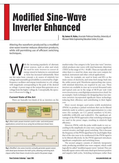
Again, look at what he is doing. This is nothing more than a modified sine wave inverter without any isolation. This is not a new idea, the exact concept the guy is talking about was proposed in this 2006 article by James Hahn.

 
Last edited:
It is funny how people are trying to make 85%+ efficient inverters more efficient when the first problem I have with AC circuits today is the lack of active power factor correction. From LED lights to TV's, none of them have any power factor correction and some of them have a PF of 0.50. This means I have to provide a 50 watt lights with 100 watts of AC power due to their conversion inefficiency that normally is not noticed when used on grid. My Renogy inverter uses < 1 amp when idle and is > 85% efficient. It makes more sense to me to fix the loads that use inefficient switching power supplies before looking at the inverter. I have a pool pump that used to pull ~528 watts off the inverter/generator and only 330 watts off the grid. Adding a 80uf cap dropped the battery draw to about 350 watts.

Without changing the inverter, I dropped the battery draw by 180 watts by fixing the power factor issue, not the inverter inefficiency. Even if the inverter was 100% efficient, a 0.62 is still a 38% (200 watt) waste of energy to run a 328 watt device. Power factor of switching power supplies is even worse and much more difficult to overcome. My 75amp charger is a unity PF of 1.0.. IOTA 55 AMP without APFC draws more amps off the generator than the 75amp with.. That is what I'd like to see go mainstream, An adjustable APFC box to add to switching power supply loads that waste my solar power.
 
Maybe I should write a post and someone can add it to 'resources'?

I used a KillOWatt meter, recorded Amps / Watts / Volts and went to this website to get the PF and capacitor needed. This only works for motors, not harmonic loads.


I added the capacitor the relay circuit so it will only be in circuit when the pump is turned on. The capacitor that is required MUST be a run cap, not a starting cap. CBB-xx, not CB-xx (starter) because a starting capacitor will overheat and vent very quickly.. Once the magic gas is out, nothing works.. :D

Here is a youtube video I found..
 
Just for fun I checked my Dell Laptop. My Kill-a-Watt says it has a .91 Power factor. I suspect the switching power supplies on most modern electronics are going to be similar.
 
Just for fun I checked my Dell Laptop. My Kill-a-Watt says it has a .91 Power factor. I suspect the switching power supplies on most modern electronics are going to be similar.
I would love for that to be true.. 4 14 watt lights installed, 110 watts off the inverter. .91 is the best of them, not the worse.. > 0.90 is considered to have APFC in the PS..
 
I have no doubt eliminating the transformer accounts for a nice efficiency gain, but it is also true that switching FETs on and off takes more energy than just leaving them on or leaving them off. (Higher switching frequency = more energy loss). Consequently, I can easily believe the lower frequency contributes to the efficiency.

How much each contributes is hard to say, but since traditional inverters can get to the 95% range, it is going to take efficiency gains in every aspect of the system to get to 99.5%

The 95% number is also why I said I would just do more solar if I needed 5% more energy.... adding a panel or two it is a lot easier than building one of these.
I have designed non-isolated (transformerless) DC/DC converters that run at 98%+ efficiency and are swtiching at about 250Khz. The switching losses in the MOSFETs are certainly a big consideration, but between the devices themselves, the circuit design, and the physical PCB layout can clearly be managed even at somewhat high frequencies. These designs still rely on inductors which contribute a lot to the losses.

Some of my designs that needed to be really small run at 1Mhz which allows the magnetics to be very small. Those can still be in the 96%+ over a rather wide range with 98% peaks. Nothing exotic or special about these designs - fairly typical stuff with typical components.
 
I would love for that to be true.. 4 14 watt lights installed, 110 watts off the inverter. .91 is the best of them, not the worse.. > 0.90 is considered to have APFC in the PS..

I just tried my comcast cable box.... It has a power factor of .61 and running ~ 20 Watts. Not only it is using up power when not in use, it is wasting 39% of what I pay for. I really need to do something about that wasted power. I am on grid and just throwing money away. The first thing is to put a timer on it so it is never running when I am never watching the TV. In fact, I have a whole stack of AV equipment that could go on such a timer. I just need to set it up so it is easy to turn on if I want to use it at times it would normally be off.
 
Back
Top