diy solar

diy solar

About inverter grounding, cable size, scaling consideration

SFR

New Member
Joined
Jun 13, 2023
Messages
8
Location
SLC, Utah
All,

I am stumped, questions below.

The attached image roughly describes the system. Here are text details:

PV: 4x 100w Rich Solar 2s2p
SCC: Victron 100/30
Breaker: Blue Sea 7182, 40a
Busses: 300a 4-stud from Current Connected
Cut-off Switches: Blue Sea 6006
Batteries: 4x SOK 100ah
Shunt: Victron Smartshunt, with bluetooth dongle
Charger: Victron IP22 12v, 30a
Inverter: Renogy 2000w pure sine wave
Auxiliary AC panel: Reliance #104B1, 4 circuits

Cable Sizes: PV to cut-off switch to SCC = 10 awg
Cable Sizes: SCC to breaker to bus = 6 awg
Cable Sizes: Battery bank connections = 2/0 awg (9” each)
Cable Sizes: Battery to 200 amp fuse to bus = 2/0 awg
Cable Sizes: Bus to inverter = 4 awg (Renogy supplied)

Key:
Red = positive
Blue = Negative
Green = ground ???

* System is not tied into grid

** Object of the system is to voluntarily (manually) supplement ‘house’ AC power as a 12v system to save costs, for back-up and proof of concept

*** BUT I would like the potential to upgrade to 24v system if this experiment works out


QUESTIONS:

Should cable from bus to Renogy inverter be larger than the 4 awg that Renogy supplied (my sense is yes, make it 2/0 but perhaps Renogy knows what they are doing)?

Does inverter need to be grounded if it is being connected to house AC with Reliance transfer panel?

Is it OK to solder the terminals on the 2/0 awg cabling (my current crimper only works to 1/0)?

Do I need a battery balancer for the four 100a/h LiFePo batteries?

If the concept works for me and I wish to upgrade to a 24v system, which components must be changed? Inverter, obviously, and batteries rewired to 24v configuration, and additional PV panels ... anything else?


Thank you for being patient as I walk through this,
SFR
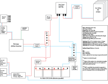


Solar Schematic 5.png
 
PV: 4x 100w Rich Solar 2s2p

That’s not much solar for this system…
Breaker: *** BUT I would like the potential to upgrade to 24v system if this experiment works out


QUESTIONS:

Should cable from bus to Renogy inverter be larger than the 4 awg that Renogy supplied (my sense is yes, make it 2/0
Yes! Much bigger - I would use 2/0 to match the other 2/0 wires.

perhaps Renogy knows what they are doing)?
They save money by putting a cheap cable in the box - not a right sized cable.

Does inverter need to be grounded if it is being connected to house AC with Reliance transfer panel?
You need to research neutral- ground bonds and find out if/what Renogy did. (Important step!)

Is it OK to solder the terminals on the 2/0 awg cabling (my current crimper only works to 1/0)?
Not as good - but that will work - especially because your loads will not be really large…
Do I need a battery balancer for the four 100a/h LiFePo batteries?
At a 12v system- no they will self balance -
If the concept works for me and I wish to upgrade to a 24v system, which components must be changed? Inverter, obviously, and batteries rewired to 24v configuration, and additional PV panels ... anything else?
You will need to reprogram the mppt.

Also when looking at more panels- consider getting much bigger (and cheaper per watt) panels- you may want/need to setup a second solar array (so maybe run the wires now?) to keep using the current 100w panels.

Overall your plan looks good. Except I don’t think 400w of Solar will provide lots of power for you.

Just research the neutral- ground bond to make sure if any of the120v loads has an issue and blows up that it will trip the breaker and not just leave the frame hot.

Good Luck
 
That’s not much solar for this system…

Yes! Much bigger - I would use 2/0 to match the other 2/0 wires.


They save money by putting a cheap cable in the box - not a right sized cable.


You need to research neutral- ground bonds and find out if/what Renogy did. (Important step!)


Not as good - but that will work - especially because your loads will not be really large…

At a 12v system- no they will self balance -

You will need to reprogram the mppt.

Also when looking at more panels- consider getting much bigger (and cheaper per watt) panels- you may want/need to setup a second solar array (so maybe run the wires now?) to keep using the current 100w panels.

Overall your plan looks good. Except I don’t think 400w of Solar will provide lots of power for you.

Just research the neutral- ground bond to make sure if any of the120v loads has an issue and blows up that it will trip the breaker and not just leave the frame hot.

Good Luck

Thank you very much. This is exactly the guidance and insight I was seeking.
 
That’s not much solar for this system…

Yes! Much bigger - I would use 2/0 to match the other 2/0 wires.


They save money by putting a cheap cable in the box - not a right sized cable.


You need to research neutral- ground bonds and find out if/what Renogy did. (Important step!)


Not as good - but that will work - especially because your loads will not be really large…

At a 12v system- no they will self balance -

You will need to reprogram the mppt.

Also when looking at more panels- consider getting much bigger (and cheaper per watt) panels- you may want/need to setup a second solar array (so maybe run the wires now?) to keep using the current 100w panels.

Overall your plan looks good. Except I don’t think 400w of Solar will provide lots of power for you.

Just research the neutral- ground bond to make sure if any of the120v loads has an issue and blows up that it will trip the breaker and not just leave the frame hot.

Good Luck


From what I am able to surmise from the forum and the Renogy manual there is an internal bond between neutral and ground.

I used Continuity mode on my test meter; touched black lead to external neutral terminal and red lead to external ground lug and received a reading indicating a connection (if I understand this correctly).

I tested physically by connecting single battery (meter showed 13.5v) to inverter and plugged in to the transfer panel using grounded extension cord and the inverter GFC tripped, which I suspect proves existence of internal N-G bonding.

If the inverter will always be used to supply AC power from battery bank to transfer panel/main panel/AC outlets would it be OK to open the inverter and snip the bond connection, relying on the ground provided by the main house panel?


Thank you,
SFR
 
Last edited:
I hope you don't mind... but to piggy back on your post. I have the Renogy 3000w inverter and am using 4/0 battery to inverter cabling. It was recommended I run all my batteries to a bus bar and then from the bus bar to the inverter. Can I just use 4/0 from battery to batter then to inverter and not use the bus bar? I have 4 100Ah liFo. Thanks
 
@ardy564 - the best way is to land each battery onto a bus bar. A good way is to link all the positive’s together and all the negative’s together- then take positive from battery#1 and negative from battery #4.
 
From what I am able to surmise from the forum and the Renogy manual there is an internal bond between neutral and ground.

I used Continuity mode on my test meter; touched black lead to external neutral terminal and red lead to external ground lug and received a reading indicating a connection (if I understand this correctly).

I tested physically by connecting single battery (meter showed 13.5v) to inverter and plugged in to the transfer panel using grounded extension cord and the inverter GFC tripped, which I suspect proves existence of internal N-G bonding.

If the inverter will always be used to supply AC power from battery bank to transfer panel/main panel/AC outlets would it be OK to open the inverter and snip the bond connection, relying on the ground provided by the main house panel?


Thank you,
SFR
I have no idea if that is a bad idea or not. I just know there can be issues there.
 
I have no idea if that is a bad idea or not. I just know there can be issues there.

Thank you.

When I plug a box fan directly to the inverter (standard two prong AC plug) both appliance and inverter behave as expected, functioning with no faults. However, when I connect the inverter to the transfer panel, which is, of course, grounded, it trips the internal GFCI in the inverter (indicated by the constant yellow LED after shutdown).

This suggests a ground fault of some kind, probably a violation of the, "There can be only one" rule.

I believe the solution is to snip the internal G-N bond wire but I will need to read more before doing so.
 
I don’t believe GFCI’s know if there is more than one N-G bond. They just know if current is leaking.
 
Back
Top