diy solar

diy solar

AC Combiner Box for 2 or more 18kPV in Parallel

WattAboutThat

New Member
Joined
Dec 15, 2021
Messages
123
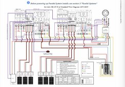
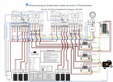
Will Prowse’s Blue Print for Parallel EG4 6000XP

I watched Will Prowse’s video on paralleling TWO EG4 6000XP inverters. It was great info as usual.

I need assistance on the folliwing:

I am trying to parallel Two EG4 18kPV Inverters.
Each can output 200Amps 240V.
I need to combine both outputs into
one which would result in 400Amps,
via sone kind of AC Combiner box, or bus, or multi blade switch, to then go to a distribution panel.

I have no idea how to do this, or what to search for. Everything that uses breakers appears to be thousands of dollars.

So I want to be safe but not go broke in tge process.

Please advise.

I found a 3 blade switch on amazon for $170,
but i wasn’t sure that would be safe, with exposed blades.

Looking for solutions.

Thanks.
 
I am trying to parallel Two EG4 18kPV Inverters.
Each can output 200Amps 240V.
Not quite; each unit outputs max 50 amps 240V. If you're doing grid passthrough, it'll output 50+50=100 Amps of inverter and pass through grid power to make up the difference, up to 200A total.

Basically, There's a good wiring diagram on page 35 of the current 18KPV Manual that shows the two-inverter setup with grid combiner and load combiner panels. You need both, and you breaker the 18KPV's to 60 amps each (meaning if you go over 120 amps load, you'll trip breakers). I'm not sure if you could size the breakers up to 100A to do parallel grid passthrough; I've never tried parallel inverters with grid passthrough to get 160A of continuous load (100 amps from the 18KPV's and 60 amps from the grid). That might be a good demo for @SignatureSolarJames to set up at the shop and do a youtube video on?

Cheers, and good luck!
1702719449556.png
 
Not quite; each unit outputs max 50 amps 240V. If you're doing grid passthrough, it'll output 50+50=100 Amps of inverter and pass through grid power to make up the difference, up to 200A total.

Basically, There's a good wiring diagram on page 35 of the current 18KPV Manual that shows the two-inverter setup with grid combiner and load combiner panels. You need both, and you breaker the 18KPV's to 60 amps each (meaning if you go over 120 amps load, you'll trip breakers). I'm not sure if you could size the breakers up to 100A to do parallel grid passthrough; I've never tried parallel inverters with grid passthrough to get 160A of continuous load (100 amps from the 18KPV's and 60 amps from the grid). That might be a good demo for @SignatureSolarJames to set up at the shop and do a youtube video on?

Cheers, and good luck!
View attachment 183301
I'm basically going to be implementing this diagram in a couple of weeks. It is still unclear to me why the breakers in the combiner panels are only 60A. If you only planning to use the 50A output with the temporary several minute surges when PV power is present, then I get it. However, this chokes off your ability to do full grid passthrough. Diagram 4.4 on the previous page in the manual is for a single inverter and it has not such 60A limit. It would make more sense to me (as was mentioned) that these breakers should be 100A which would assume the paralleled inverters know how to balance the passthrough. Am I missing something here?
 
I'm basically going to be implementing this diagram in a couple of weeks. It is still unclear to me why the breakers in the combiner panels are only 60A. If you only planning to use the 50A output with the temporary several minute surges when PV power is present, then I get it. However, this chokes off your ability to do full grid passthrough. Diagram 4.4 on the previous page in the manual is for a single inverter and it has not such 60A limit. It would make more sense to me (as was mentioned) that these breakers should be 100A which would assume the paralleled inverters know how to balance the passthrough. Am I missing something here?
Many ways to set up I imagine. But if the 18K is similar to the Sol-Ark, here is a simpler way to wire it. I just use distribution blocks. You can add a transfer switch, but with the Sol-Ark it isn’t necessary. And if I have to remove/work one of the inverters for whatever reason, I just shut power down at the meter and do a quick wire rearrangement, then turn power back on. Having a transfer switch would eliminate losing power for ~15 minutes for me. But probably necessary if you have others that would need power in your absence if an inverter failed.
 

Attachments

  • IMG_2504.jpeg
    IMG_2504.jpeg
    270.1 KB · Views: 24
  • IMG_2503.jpeg
    IMG_2503.jpeg
    275.1 KB · Views: 25
Many ways to set up I imagine. But if the 18K is similar to the Sol-Ark, here is a simpler way to wire it. I just use distribution blocks.
 
I’m familiar with Polaris. I just preferred distribution blocks that are fastened down and labeled in a wire trough.
 
I'm basically going to be implementing this diagram in a couple of weeks. It is still unclear to me why the breakers in the combiner panels are only 60A. If you only planning to use the 50A output with the temporary several minute surges when PV power is present, then I get it. However, this chokes off your ability to do full grid passthrough. Diagram 4.4 on the previous page in the manual is for a single inverter and it has not such 60A limit. It would make more sense to me (as was mentioned) that these breakers should be 100A which would assume the paralleled inverters know how to balance the passthrough. Am I missing something here?

Have this exact question! 🤩

The grid and load AC combiner panels in the manual schematic show 60amp backfed breakers from the Eg418kpv inverters. Definitely limits grid assist passthrough current.. Is there any reason they should not be 100amp backfed breakers or as suggested below just just Polaris multitaps?

Cheers!
Paul
 
I'm basically going to be implementing this diagram in a couple of weeks. It is still unclear to me why the breakers in the combiner panels are only 60A. If you only planning to use the 50A output with the temporary several minute surges when PV power is present, then I get it. However, this chokes off your ability to do full grid passthrough. Diagram 4.4 on the previous page in the manual is for a single inverter and it has not such 60A limit. It would make more sense to me (as was mentioned) that these breakers should be 100A which would assume the paralleled inverters know how to balance the passthrough. Am I missing something here?
I was looking through the Sol-Ark and EG4 Manuals, and the way grid pass-through is set up, I don't think I see a reason why you couldn't do 200A Breakers to get the full pass-through. I'm not sure why the EG4 manual shows 60A breakers; the Sol-Ark manual does show the correct sizes in their chart. I'd love to see a Signature Solar demo of 200A passthrough in parallel, just to show how it's done.1707202974606.png
 
The breakers are sized to protect the cables, the inverter should look after itself.
So if you want the full 200A pass through you should be using 3/0 copper or 4/0 aluminum cables.
 
So just so I understand, (first post here) I could use distribution blocks to feed all three of my new 18KPV inverters together? My plan was to just pass the L1,L2,N,Gnd lines from inverter to inverter with blocks using 4/0 wire. Same for load back to my 200amp farm panel.
 
Bit more info required.
Is your grid supply 200A and you are using 3x 18k to have a maximum inverter output of 150A ?

I don't know if this is a valid option.... 200A grid to a single 18k as it can handle the full 200A bypass and just parallel the outputs.
 
Many ways to set up I imagine. But if the 18K is similar to the Sol-Ark, here is a simpler way to wire it. I just use distribution blocks. You can add a transfer switch, but with the Sol-Ark it isn’t necessary. And if I have to remove/work one of the inverters for whatever reason, I just shut power down at the meter and do a quick wire rearrangement, then turn power back on. Having a transfer switch would eliminate losing power for ~15 minutes for me. But probably necessary if you have others that would need power in your absence if an inverter failed.
Why are L1and L1 swapped at the inverter inputs?
 
Why are L1and L1 swapped at the inverter inputs?
Not sure I understand the question. In the US, we have single split-phase. L1 and L2. 120V and 120V. together 240V

Are you addressing the scenario of more phases with paralleled inverters? 208V?
 
I’m planning a 200-A main breaker in the first box after the meter. 200-amp breakers in that box will goto each of the (two) inverters Grid connections. The Load connections will go to another similar box (with nothing on the main lugs) through another pair of 200A breakers. Then all of my sub-panels will be fed from this AC Combiner box. Does that make sense? I figured that way I can switch inverters off as required to service them by using all those breakers.

I’ll use 3/0 copper for all the interconnects.

I would draw this out but my drawing skills aren’t legendary. 🤓

What happens if I switch out one or the other of a parallel set of 18Kpv inverters (or if one fails)? Will the other keep working or shut down?
 
Not sure I understand the question. In the US, we have single split-phase. L1 and L2. 120V and 120V. together 240V

Are you addressing the scenario of more phases with paralleled inverters? 208V?
In the drawing the red wire goes to L1 on one inverter and L2 on the other inverter.
 
I’m planning a 200-A main breaker in the first box after the meter. 200-amp breakers in that box will goto each of the (two) inverters Grid connections. The Load connections will go to another similar box (with nothing on the main lugs) through another pair of 200A breakers. Then all of my sub-panels will be fed from this AC Combiner box. Does that make sense? I figured that way I can switch inverters off as required to service them by using all those breakers.

I’ll use 3/0 copper for all the interconnects.

I would draw this out but my drawing skills aren’t legendary. 🤓

What happens if I switch out one or the other of a parallel set of 18Kpv inverters (or if one fails)? Will the other keep working or shut down?
If they’re like the Sol-Arks, when you unparallel them in your scenario, do you need to change the operating inverter back to single inverter operation.
 
That was for the two/multi phase operation. Look at the second diagram for single phase.
Now I get it, thanks! Thought there might be some advantage to running them 180 degrees out of phase to deal with unbalanced loads or something.
 
Back
Top