RCinFLA
Solar Wizard
- Joined
- Jun 21, 2020
- Messages
- 3,565
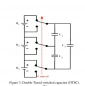
Video not precisely correct, there are two parallel banks of capacitors sequenced, but principle of operation is correct.Hi did anyone reverse engineer the schematic for these Chinese switched capacitor units like heltec etc
There are small series resistors to limit current, ('U') marked resistors connected to cells.
Net stack voltage on series capacitor stack will be slightly lower due to losses so there will be some small amount of net discharge to total battery stack.
All done in full parallel sequence.
1) collect each individual cell voltage on capacitors.
2) Pool the caps together to equalize their charge voltage.
3) Separate charge equalized caps and reapply to each cell
I would not permanently leave this balancer connected to battery pack all the time. If input capacitor shorts out or has significant leakage current you will put your battery pack at risk of damage, which your BMS has no control over preventing. There is a large ripple current stress on these capacitors for significant SOC difference between cells. Large ripple current with capacitor ESR results in capacitor internal heating.
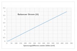
Due to 5 to 10 mV of cell overpotential voltage for very small cell current, there is the same limitation on balancing cells that just passively paralleling cells have for balancing.
Last edited: