


You are using an out of date browser. It may not display this or other websites correctly.
You should upgrade or use an alternative browser.
You should upgrade or use an alternative browser.
Another Inverter Inrush Current Limiter
- Thread starter tinyt
- Start date
48V 3.4KVA DIY toroidal inverter with 6x 10000uF 63vdc capacitors. Will be replacing the 4S 100AH AGM batteries with LiFePO4/BMS combination, so I was thinking that an automatic limiter will be needed to protect the BMS. I have a box full of 2 ohms 25 watts resistors, so I will be using them as the current limiter. From amazon, the 200A contactor is $37 and the 10A relay is about $2.40. PCB circuit will be on a protoboard.How large is the inverter? What dc voltage? I see what may be an expensive, complicated solution to a minor problem that can be ignored.
Last edited:
I don't know all the detailed stuff. But my real life experience is with 690 amp hour bank at 12 volts powering a 2000W inverter. I use a 300 amp Blue Sea disconnect switch. I have not had a problem with inrush current to the inverter for more than 3 years now. I do switch off many times during the year.
Thanks for the info.I don't know all the detailed stuff. But my real life experience is with 690 amp hour bank at 12 volts powering a 2000W inverter. I use a 300 amp Blue Sea disconnect switch. I have not had a problem with inrush current to the inverter for more than 3 years now. I do switch off many times during the year.
Currently I have a 100 amp manual inrush limiter with a 48V 100AH AGM bank driving a 3.4 kva toroidal home brew inverter which has a total of 60000uF capacitor. And I never have a problem, but I power cycled it a few times only during testing.
My concern is when I upgrade my battery bank to LiFePO4 with BMS which I think can re-cycle power without my control, it might not be able to handle the practically dead short that the 60000uF capacitor ( 6x 10000uF) will present. I think the 60000uF is overkill for 3.4kva but that is what I started with when I was building my home brew and it is difficult now to unsolder some from the pcb.
Quattrohead
Solar Wizard
My jbd BMS has a precharge circuit built in, works great.
Thanks for the info. I assume the precharge is from the SCC to the battery. Is there a discharge overcurrent limiter from the battery to the inverter?My jbd BMS has a precharge circuit built in, works great.
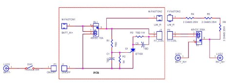
I received all of the parts I ordered more than a week ago, but was too busy to do anything. The contactor came from Amazon. I did the following measurements:
Coil resistance: 125 ohms.
Pick up voltage: 40 volts minimum.
Drop out voltage: about 15 volts.
So, at 48 volts, contactor coil power draw is (48 x48)/125 = 18.4 watts. Coil current = 48/125 = 0.384A
If I arbitrarily choose a holding voltage of (Drop out voltage +10) = 15 +10 = 25 volts, the coil current will be 25/125 = 0.2A. R4 in the schematic will be (48 -25)/0.2 = 115 ohms. And contacor coil circuit power draw is ( 48 x .2) = 9.6 watts.
I still don't like it. Also, the calculation is for 48 volts which is at the low end of the battery pack.
I will still assemble the circuit and do functional test. But will probably re-design to eliminate the contactor or go with a simple rotary switch like this.
Update:
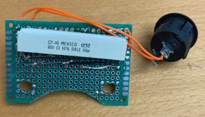
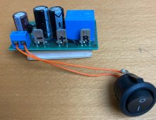
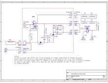
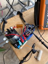
Finally assembled the protoboard. Most of the components were left over from previous projects except for the relay and scr. Attached schematic has the updated component values. Pictures of the protoboard are also attached.
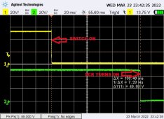
I performed functional test substituting a resistor for the contactor coil. I used an oscilloscope to verify delay timing. 'scope screen capture is also attached.
Finally assembled the protoboard. Most of the components were left over from previous projects except for the relay and scr. Attached schematic has the updated component values. Pictures of the protoboard are also attached.
I performed functional test substituting a resistor for the contactor coil. I used an oscilloscope to verify delay timing. 'scope screen capture is also attached.
Attachments
Roswell Bob
Solar Enthusiast
Yes, your bus seems to be rather large. I converted over from led-acid to LiFePO4 and have the same concerns. I figure a good chance the BMS will smoke or the Class T fuse will clear.
I used a 0.3 ohm NTC to limit the current and put a contactor right across it. The contactor gets its 48v from the bus cap side of the inrush limiter - so there is enough of a delay(I hope) to get caps charged before contactor pulls in. I will put a scope on it this weekend, but powered it up a few times without any probs. I'm running I think 4x6800uF on a 6kW Growatt inverter.
Why did you choose SCR rather than mosfet?
Do you have any info to share on your DIY inverter?
thanks
Roswell Bob
Bud Martin
Solar Wizard
- Joined
- Aug 27, 2020
- Messages
- 4,844
No snubber diode for the DC relay coils?
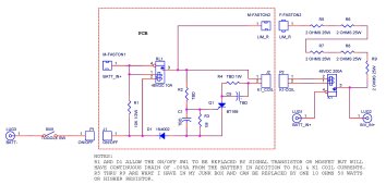
SCR Q1 is used as a latch when used in DC circuit, it will stay on once it is turned on, to turn it off the power has to be removed.
SCR Q1 is used as a latch when used in DC circuit, it will stay on once it is turned on, to turn it off the power has to be removed.
I used an scr because for me that is the simplest way of creating a time delay with an output capable of driving a relatively heavy load (lamps, relays, etc.). Because of the continuous power draw of the contactor coil which to me is high, I am thinkling of replacing the contactor with mosfets but still retain the SCR for time delay function. For now, I will complete testing this circuit when I recieve the 10 ohms power resistor I ordered. I already have setup my left over 5 x 10000 uF in parallel for testing.Yes, your bus seems to be rather large. I converted over from led-acid to LiFePO4 and have the same concerns. I figure a good chance the BMS will smoke or the Class T fuse will clear.
I used a 0.3 ohm NTC to limit the current and put a contactor right across it. The contactor gets its 48v from the bus cap side of the inrush limiter - so there is enough of a delay(I hope) to get caps charged before contactor pulls in. I will put a scope on it this weekend, but powered it up a few times without any probs. I'm running I think 4x6800uF on a 6kW Growatt inverter.
Why did you choose SCR rather than mosfet?
Do you have any info to share on your DIY inverter?
thanks
Roswell Bob
On the DIY inverter I will gather the files that I have and maybe create another thread.
Probably a good idea to put snubbers on the DC relay coils. The circuit is basically for one time use - at inverter power on and power off. The K1 contactor coil with its hi current draw I think will be the stronger EMI generator at power off. The resistance of RL1 coil I used is about 6K ohms, so probably not much EMI will be generated by it.No snubber diode for the DC relay coils?
SCR Q1 is used as a latch when used in DC circuit, it will stay on once it is turned on, to turn it off the power has to be removed.
You are correct the circuit is DC latching. SW1 is optional, and can be jumpered so that when power is applied the SCR will latch on after the delay time.
Update:
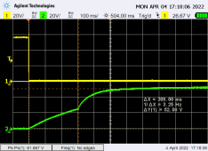
I connected five 10,000uF 63V capacitors in parallel for load and used my 48V AGM battery bank for testing. I used a 10 ohms 25W limiting resistor. I also added a diode snubber across the K1 contactor coil. Scope CH1(yellow trace) is connected to the switch and RL1 junction. Scope CH2(green trace) is connected to the positive of the load capacitors.
Looks like it works. But reliability is zero, after two tests, the scr blew open. I think the BT169 is under-rated for the contactor coil. SCR C106B with its 200V 4A rating will probably work reliably.
As I mentioned earlier I don't like the excessive power draw of the mechanical contactor. A latching (set/reset) contactor if one exists will probably be better but will make it complicated and expensive. Back to the drawing board for power mosfet substitute.
Attachments
400bird
Solar Wizard
A breaker takes no power to keep on.
The precharge circuit could be a momentary push button in series with your resistors.
The precharge circuit could be a momentary push button in series with your resistors.
That is what I have right now. But I want something automatic when I switch over to LiFePO4 with BMS.A breaker takes no power to keep on.
The precharge circuit could be a momentary push button in series with your resistors.
Attachments
Roswell Bob
Solar Enthusiast
Use the circuit I am using. A contactor and an inrush limiter.That is what I have right now. But I want something automatic when I switch over to LiFePO4 with BMS.

My two component automatic inrush limiter for charging inverter bus seems to be working just fine.
Charge relay circuit uses digikey parts A122275-ND & 570-1393-ND
 diysolarforum.com
Last edited:
Roswell Bob
Solar Enthusiast
You cannot let an SCR meander on. That is a sure way to get it to fail. You have to hit it with a good size pulse with a fast rise time so the current spreads across the device quickly.Update:
I connected five 10,000uF 63V capacitors in parallel for load and used my 48V AGM battery bank for testing. I used a 10 ohms 25W limiting resistor. I also added a diode snubber across the K1 contactor coil. Scope CH1(yellow trace) is connected to the switch and RL1 junction. Scope CH2(green trace) is connected to the positive of the load capacitors.
Looks like it works. But reliability is zero, after two tests, the scr blew open. I think the BT169 is under-rated for the contactor coil. SCR C106B with its 200V 4A rating will probably work reliably.
As I mentioned earlier I don't like the excessive power draw of the mechanical contactor. A latching (set/reset) contactor if one exists will probably be better but will make it complicated and expensive. Back to the drawing board for power mosfet substitute.
I like the ICL, it is affordable.Use the circuit I am using. A contactor and an inrush limiter.
My two component automatic inrush limiter for charging inverter bus seems to be working just fine.
Charge relay circuit uses digikey parts A122275-ND & 570-1393-ND
But the contactor is a bit expensive for me. Besides its continuous power draw of 15.8 watts @48volts is too high for me. In comparison, my DIY 3.4KW inverter has the following idle power draws: Electronics - 4 watts, toroid - 10 watts.
Similar threads
- Replies
- 1
- Views
- 143
- Replies
- 0
- Views
- 318
- Replies
- 3
- Views
- 354
- Replies
- 32
- Views
- 1K