curiouscarbon
Science Penguin
- Joined
- Jun 29, 2020
- Messages
- 3,024
?doneVery nice. Thanks for providing the code. Suggestion: parameterize the number of cells:
#define NUM_CELLS 16
at the top after the include


?doneVery nice. Thanks for providing the code. Suggestion: parameterize the number of cells:
#define NUM_CELLS 16
at the top after the include
I did the esp32 to esp32 test again and the uart is still working.I read the same thing... but, after I connected it to the tx and rx of the bms. ?
...I plan to do a other esp32 to esp32 serial test to be sure it still works.
Query 0x04 Cell Voltages
7 bytes available to read
[WAIT_FOR_STOP_BYTE]: DD

Checksum did not calculate!
  Calculated: FFFD
  Received: FD77
[WAIT_FOR_START_BYTE]:  A5
[WAIT_FOR_START_BYTE]:  4
[WAIT_FOR_START_BYTE]:  0
[WAIT_FOR_START_BYTE]:  FF
[WAIT_FOR_START_BYTE]:  FC
[WAIT_FOR_START_BYTE]:  77
The rx_state is: 0...
Voltage: 0.000 voltsQuery 0x03 Basic Info
7 bytes available to read
[WAIT_FOR_START_BYTE]: DD
[WAIT_FOR_CMD_CODE]: A5
[WAIT_FOR_STATUS_BYTE]: 3
RX error! Status byte should have been 0x00 or 0x80!
[WAIT_FOR_LENGTH]: 0
[WAIT_FOR_DATA]: FF, rx_data_index=0
[WAIT_FOR_CHECKSUM_MSB]: FD
[WAIT_FOR_CHECKSUM_LSB]: 77
The rx_state is: 7...In the spirit of elmination and substitution, did you try serial communication with another device?[UPDATE]
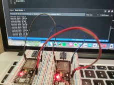
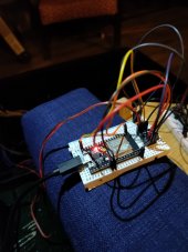
I received the logic level converters from amazon and built two boards up for testing. Neither work properly. These are the converters that I'm using. I've attached a photo of one of them all wired up.
Looks like the bms is responding now. However, the bms.cpp lib is reporting this back from a cell voltage request
Code:Query 0x04 Cell Voltages 7 bytes available to read [WAIT_FOR_STOP_BYTE]: DD Checksum did not calculate! Calculated: FFFD Received: FD77 [WAIT_FOR_START_BYTE]: A5 [WAIT_FOR_START_BYTE]: 4 [WAIT_FOR_START_BYTE]: 0 [WAIT_FOR_START_BYTE]: FF [WAIT_FOR_START_BYTE]: FC [WAIT_FOR_START_BYTE]: 77 The rx_state is: 0... Voltage: 0.000 volts
And this from the basic info request.
Code:Query 0x03 Basic Info 7 bytes available to read [WAIT_FOR_START_BYTE]: DD [WAIT_FOR_CMD_CODE]: A5 [WAIT_FOR_STATUS_BYTE]: 3 RX error! Status byte should have been 0x00 or 0x80! [WAIT_FOR_LENGTH]: 0 [WAIT_FOR_DATA]: FF, rx_data_index=0 [WAIT_FOR_CHECKSUM_MSB]: FD [WAIT_FOR_CHECKSUM_LSB]: 77 The rx_state is: 7...
Troubleshooting that I've done...
The converter requires both 5v and 3.3v input voltage and ground on both side, as far as I understand from reading the amazon listing and questions from users.
- tested ground cont
- tested 5v output from the esp32
- tested 3.3v output from the esp32
- Confirmed that tx and rx are connected to rx and tx respectively. I was certain this wasn't the issue since there appears to be actual data coming back from the bms.
- Try the other module
Yessir.In the spirit of elmination and substitution, did you try serial communication with another device?
uint32_t last_update;

HardwareSerial HWSerial(2); // Define a Serial port instance called 'Receiver' using serial port 2

#define Txd_pin 17
#define Rxd_pin 16


void setup() {
    delay(500);

    Serial.begin(115200);
    HWSerial.begin(9600, SERIAL_8N1, Txd_pin, Rxd_pin);

    while (!Serial) {  // Wait for the debug serial port to initialize
    }
    while (!HWSerial) {  // Wait for the BMS serial port to initialize
    }

    last_update = millis();

}

void loop() {
  if (millis() - last_update >= 2500){
    Serial.println("----------------------");
    Serial.println("sending read request");
    uint16_t checksum = 0;
    HWSerial.write(0xDD);
    HWSerial.write(0xA5);
    HWSerial.write(0x03);
    checksum += 0x03;
    HWSerial.write(0);
    checksum = (uint16_t)((0x10000UL) - (uint32_t)checksum);

    uint8_t checksum_msb = (uint8_t)((checksum >> 8) & 0xFF);
    HWSerial.write(checksum_msb);

    uint8_t checksum_lsb = (uint8_t)(checksum & 0xFF);
    HWSerial.write(checksum_lsb);

    // Write the stop byte, 0x77
    HWSerial.write(0x77);


    Serial.println("delaying read....");

    delay(2000);

    int bytes_available = HWSerial.available();
    if (bytes_available > 0) {
      for (int i=0; i < bytes_available; i++) {
           int c = HWSerial.read();
           Serial.print("read byte ");
           //Serial.print(c);
           //Serial.print(" ");
           Serial.println(c, HEX);

        }
    }
    last_update = millis();
  }
}----------------------
sending read request
delaying read....
read byte DD
read byte A5
read byte 3
read byte 0
read byte FF
read byte FD
read byte 77I don't have an answer. That part I just copied from the bms.cpp file. Based on the protocol file, what would you suggest I do?I don't get the masking you're doing on the checksum. If you shift an 8-bit number 8 bits to the right, you've shifted all of the bits off. It only works to get MSB if it fills on the left with a duplicate of the MSB on each shift. Likewise, masking the checksum with 0xFF just gives you the original checksum.
(uint8_t)((checksum >> 7) & 0xFF)
would give you the MSB in the LSB position.
(uint8_t)(checksum & 0x01)
would give you the the LSB (only) in the LSB position
I don't get the masking you're doing on the checksum. If you shift an 8-bit number 8 bits to the right, you've shifted all of the bits off. It only works to get MSB if it fills on the left with a duplicate of the MSB on each shift. Likewise, masking the checksum with 0xFF just gives you the original checksum.
(uint8_t)((checksum >> 7) & 0xFF)
would give you the MSB in the LSB position.
(uint8_t)(checksum & 0x01)
would give you the the LSB (only) in the LSB position
(Not sure what the rules are for implicit casting with constants.)
Also, why this?
checksum += 0x03
Since checksumn is set to 0 a few statements earlier, this value will always be 3. So you could just initialize to 3. I have not looked at the protocol used for this, but checksum is typically the XOR of each of the bytes leading up to the checksum byte.
I don't have an answer. That part I just copied from the bms.cpp file. Based on the protocol file, what would you suggest I do?
According to the protocol doc, there's no data in the data position in a read request. The instructions that the bms should read and respond to come from the A5 (read) and the 03 (basic info). ....I think.It looks like "checksum" is a 16 bit (uint16_t) value in the code above and I believe the part of the code where it subtracts a value from "0x10000UL" presumably is how data gets into the upper (most significant) bits. Are you suggesting that only the lower (least significant) 8 bits are ever populated?
I'm not sure I'm convinced that's the problem...
It seems like kind of an odd checksum since it doesn't take into account the data being sent, but I assume that's because the message has been hard-coded.
Are you getting reliable communication at a baud rate of 115200 ?[UPDATE]
the lib works now.
On to the cloud part
Good going!! Nice!!!![UPDATE]
the lib works now.
On to the cloud part
No, haven't tried anything more than 9600. The docs don't say it can't ....but, it does say 9600 specifically works.Are you getting reliable communication at a baud rate of 115200 ?
I wish I had a good answer, but without knowing more about the protocol, it's hard to figure out how to handle the checksum, etc. Is there a document somewhere that describes this? Though if it works as-is, then the issue is moot.It looks like "checksum" is a 16 bit (uint16_t) value in the code above and I believe the part of the code where it subtracts a value from "0x10000UL" presumably is how data gets into the upper (most significant) bits. Are you suggesting that only the lower (least significant) 8 bits are ever populated?
I'm not sure I'm convinced that's the problem...
It seems like kind of an odd checksum since it doesn't take into account the data being sent, but I assume that's because the message has been hard-coded.
It's briefly covered in the JBD protocol doc (attached in a prior comment)I wish I had a good answer, but without knowing more about the protocol, it's hard to figure out how to handle the checksum, etc. Is there a document somewhere that describes this? Though if it works as-is, then the issue is moot.