diy solar

diy solar

ATS Control Wiring Question

Enigma86

New Member
Joined
Jun 1, 2023
Messages
24
Location
80021
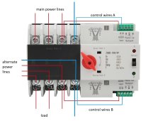
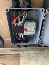
Hello. I recently put one of these Automatic Transfer Switches in my RV in front of the SP6548 so that I could use 50 amp service normally while still running 120v over to the AIO to charge batteries. Right now everything seems to be working, however, I have not wired in the control relay wiring yet for the "automatic" part of this whole thing. The idea is that during 50 or 30 amp service, normal input will be powered and should provide entire trailer + inverter with power... If I use anything else such as generator or regular 15 amp 120 I'm going to go directly to the EG4 chargeverter straight to the batteries and let the AIO supply the entire trailer with power, or when I have panels on top let the solar power it. I'd rather not have to select this back and forth manually.

IMG_0682.jpg

As you can see the control wiring ports are very small and I was wanting to make sure there shouldn't be any reason to have to use anything larger than like 16 - 14 gauge for that relay connection right, I am not aware of what kind of current should go through that and it was not included. I am indeed using this switch outside of what it was built for but I needed a 4 pole dual throw and could not find anything else that seemed to fit at at least 50 amps.
 
Is that not split phase?
Does it not have a native transfer switch?

I’d run the shorepower cord direct to the AIO and then either you plug into ‘grid’ or the generator. Then the 6548 always handles the charging and switching based on what you have the menu options set to and you choose what you’ve plugged into or not. Plus, the AIO will (should) handle your N-G bonding properly.
The reason I have it this way is that I did not want to buy 2 inverters to handle this job and I don't really need to full power of 50 amp 240 service anyways. I wanted to be setup for all kinds of power scenarios since I'll be traveling around, so the chargeverter will let me connect if all I'm offered is 15 amp service at somebodies house but yet I'll still be able to run AC units and things of that nature. If I did not do it this way and ran all power through the AIO at all times I would get stuck with only 15 amps of service to charge batteries/run the trailer with. Also if I did not do it this way I wouldn't have gotten to charge batteries off of 50 amp service at a park without buying the second inverter.

I almost had it all installed how you're saying until I realized that utility mode only let me use the utility electricity and that I couldn't pull from batteries at all.

Also, I will not have any solar panels on the rv until likely December this year or so and I'm going to be living full time in it so I wanted more options sooner than that. But even with those there are clouds to consider. I felt like this configuration let me use the absolute most possibilities of power situations.
 
Even if you are on a 15A cord you can set most AIOs to charge batteries while running off batteries in the scenario I described.
Perhaps I’m wrong but I don’t believe I’ve used any pass through amps with my AIO, merely battery charging. Simpler still, your 15A cord run directly to a separate battery charger is an inexpensive, viable solution.
My opinions; how I’d do it. Ymmv
 
I'm pretty sure that with the AIO on, the batteries will not get charged unless it is in utility mode. And if you're in utility mode then you have to use utility bypass to power things. At this point it doesn't really matter anyways because I've already bought the chargeverter and so I can get things done no matter what with it.

But my question is just simply about the control wiring on the switch. I'm just trying to verify that there should be no real large current on that line and could use something like 16 gauge wire to be able to let the switch operate in automatic mode.
I have two of these in my system, one three phase and the other single phase. There is almost no current going in the control wiring. You can use a very small wire to do it. I have 14 gauge on mine but just is because i have a lot of it. 16 gauge is perfectly fine.
 
I have two of these in my system, one three phase and the other single phase. There is almost no current going in the control wiring. You can use a very small wire to do it. I have 14 gauge on mine but just is because i have a lot of it. 16 gauge is perfectly fine.
Thank you so much, since you have these I have more questions for you then. The A/B lights are supposed to be on when the control wiring is in correct? I ended up just guessing on the wiring and accidentally went a tad too big but everything seems to be in like its supposed to but when I switch to auto the switch always goes to the backup power no matter what is coming in on the main power. AR is supposed to be one of the phases and AN is the neutral correct?
 
Thank you so much, since you have these I have more questions for you then. The A/B lights are supposed to be on when the control wiring is in correct? I ended up just guessing on the wiring and accidentally went a tad too big but everything seems to be in like its supposed to but when I switch to auto the switch always goes to the backup power no matter what is coming in on the main power. AR is supposed to be one of the phases and AN is the neutral correct?
Yes as soon as you put the control wiring in it the correspondent light turn on. Correct, AR is the phase and AN is the neutral.

If you have manual mode (right black vertical switch), the control wiring has no effect and you switch between sources turning manually the red lever.

If you have auto mode (same right black switch in the down position), then you need to do the wiring to the AR, AN, BR, BN, and have both lights on. Then you can switch the red lever to whatever source of power you want to be the priority, and the ATS will automatically get the priority power when the control wire for that source has voltage, and if the control wire for that source is off, then the ats will go to the other source if the control wire for the other has voltage.
 
Yeah... for some reason mine is not working that way. It always goes to backup power for some reason.
 
Probably in yours the 'normal power' is allways the priority in auto mode, and it will go allways there first. And only when the AR AN control wires are off it switches to the 'reverse power' if the BR BN control wires have voltage.
 
Back
Top