diy solar

diy solar

Auto Transformer Bonding

To clarify
If your grid source was an ungrounded 240v single phase source. That drawing would be exactly how it should be wired.
 
The equipment can be UL listed as drawn.
But the drawing doesn't show that it's being fed from a split-phase grid.
That was in response to the overtemp remark.

Also it does show L1/L2 for split phase input. If it was 230v it would show L/N instead (kinda like our GW5KES)

1669158177382.png
 
Then this makes me even more curious about how all of the LF inverters that use this sort of setup get away with it. For instance the Growatt 12k has only L1/L2/G inputs. Does it not use an autotransformer to make the neutral leg? Wouldn't the same problem exist in all of those units?
Yes
We've had extensive conversations about those too.
I have recommended the same solution.
 
I am hoping someone from @SignatureSolarAdam or @SignatureSolarJames can chime in here. I am just trying to make sure I follow the directions.. but they kinda leave this part out where I must tie my grid neutral into my generated neutral.

@timselectric @RCinFLA What you are both saying makes electrical sense. I don't want to get kilt by stray voltage on my grounding or cause the fires...

I appreciate everyone's time on this matter.
 
An ungrounded system would be L1 and L2.
The definition of a neutral is a "grounded conductor".
So you are talking about what the NEC states here -
"Branch circuits shall not be derived from autotransformers unless the circuit supplied has a grounded conductor that is electrically connected to a grounded conductor of the system supplying the autotransformer."

Grounded conductor being neutral? If that is the case, then what would be the point of the autotransformer?

So what that means in normal human speak is - You gotta run the neutral leg from you service entrance too - we don't care that you have an auto transformer that makes that.
Exactly
 
So what that means in normal human speak is - You gotta run the neutral leg from you service entrance too - we don't care that you have an auto transformer that makes that.
The only purpose of the autotransformer is to provide split-phase configuration from the single phase inverter. They (Chinese Engineers) have just come up with the wrong solution. (When it comes to our grid system)
 
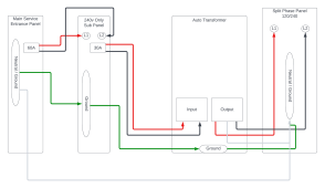
Auto Transformer Connection from Service (1).png

So this is how the circuit should look then? I mean, this is fine because I can still feed the AT from my offgrid 240V only inverter and be compliant + safe.
 
So as long as I run a 4 wire split phase service to the sub panel I am providing power to that I wasn't trying to have to run split phase power to - I can use my AT. LOL

Well I did say it would be entertaining.
Sadly yes, that's the case.
 
Main panel ground-grid neutral connect and auto transformer/aux panel ground-aux panel neutral connection means grid neutral is connected to aux panel neutral. The common connection between the two neutrals is done via the common ground wire.
 
Then this makes me even more curious about how all of the LF inverters that use this sort of setup get away with it. For instance the Growatt 12k has only L1/L2/G inputs. Does it not use an autotransformer to make the neutral leg? Wouldn't the same problem exist in all of those units?
A UL approved LF inverter like Xantrex, Outback, and others (not Growatt, AIMS, or like) check for amount of grid imbalance current carried by output center tapped neutral on transformer.

If grid neutral imbalance correction current gets too great, more than a couple of amps, the inverter releases from grid. It is just another criteria placed on grid, like grid voltage and frequency range.
 
Last edited:
I think if the relay in inverter which disconnects L1/L2 from grid also bonded N of auto-transformer to Ground, then everything would be hunky-dory.

Or this AT could be used in a strictly off-grid system.

What I haven't seen is how to use it with the inverter and grid input, without causing either "objectionable" current in ground or trying to rebalance the grid.
Right
That's why I added the relay to disconnect the autotransformer in bypass mode.
But haven't found a way to do it with the US version sold by Signature Solar. Because it doesn't have the European N/G bond. Which is how I trigger my disconnection.
 
Back
Top