diy solar

diy solar

Autotransformer

snoobler

Solar Honey Badger
Joined
Jul 10, 2020
Messages
8,387
Location
HBR, AZ
@the_colorist

This new post is for you rather than hijacking our Argentinian's thread.

There was another discussing in another thread about the Victron autotransformer with seemingly ambiguous instructions. It has a figure that appears to permit 120VAC input and 240VAC split phase output. Is this correct?

My original plan was to wire my 2X Quattro 5K in 240 split phase; however, that requires me to make sure my panel utilization is sufficient balanced between the two legs/inverters.

It would seem a better option to parallel them as 120VAC with input into an autotransformer and get 240 split phase out that is less sensitive to panel balancing.

Thoughts?
 
It is not too hard to relatively well balance out the 120vac branches and the major power items are usually 240vac anyway.

You would be better off to just use the two inverters for split phase 240v without added transformer. Transformer eddy current losses will add a few watts of constant loss and may cause inverter PWM filter to create more loss within inverter. Transformer will give you another 2-5% transmission loss, not to mention wallet loss for transformer cost. Transformer will also hurt the surge load capability.
 
I would put two inverters on the two phases, and maybe add an autotransformer as well to share power.
Among other things, this will help carry enough power to trip a breaker rather than shut down the inverter.
I have a 9000VA transformer I plan to use this way, but only connect when off-grid.

I looked at the schematic for SMA's Autoformer. It has overload or over-temp protection to disconnect one phase. I don't like that because having only one phase of a split-phase panel can cause brownout to 240V loads and 120V loads on the phase that is off.
I prefer to shut everything down if either phase can't be held up.

Transformers have magnetic coupling and resistive losses. I've read that ideally an auto transformer for 120 --> 120/240V has an imbalance in turns count to correct for the voltage drop. That wouldn't be perfect, might match voltage at some load. One intended for 240V --> 120/240V would be symmetric. But line voltage tolerances are wide enough it may not matter.

You can get a lot more through a transformer with fan cooling. I took an 8" toroid and managed to put 1250W through it - enough for a 2500W 240V Sunny Boy to work with a single 120V Sunny Island. But it required lots of air. I plan to have thermostatic fan and overtemp shutoff when I use the 9000VA one. In a second application where it is the only source of neutral, I will have all power disconnect if the transformer does.
 
An auto transformer is lower cost because it can handle twice the power of a true isolation transformer of same size core. ( for 2x step up/down)

Downside is you lose the primary-secondary isolation you get with a full isolation transformer. You can wire an isolation transformer as a autotransformer and handle twice the power it handled as isolation transformer.

A little over twenty years ago I bought two new Thordarson 23V608 2,000 VA isolation transformers from Allied. They weigh 53 lbs each for just the transformer. They have two 120v primary windings and two 120v secondary windings so provide a lot of step up/down voltage or just isolation wiring options. Secondaries have couple of percent higher voltage to make up transformer loss.

I paid like $260 each back then. I just looked them up and Allied still stocks them. Just $944.33 each now, ouch !
I use them for my backup secondary 'trickle charging' Yamaha EF3000 inverter generator to get 120vac to 240vac for my inverter/chargers. I prefer to fully isolate 120v inverter generators with their floating H-bridge output.
 
@snoobler Cool, glad to post in another thread about this. I dislike hijacking threads.

There was another discussing in another thread about the Victron autotransformer with seemingly ambiguous instructions. It has a figure that appears to permit 120VAC input and 240VAC split phase output. Is this correct?

Yes, that would be true when using a 120V inverter stepped up to 120/240V on the output side of the inverter. IMO opinion a person could technically wire it so that charging would use both legs of a 240V source but I would not suggest anyone outside of another engineer try it. Simply too easy to get it wrong IMHO (no offense to anyone). Even then it greatly depends in part on the inverter used. The Victron inverter may shut down the AC input if it's getting power from both sides.

It's true the wiring is not what I would call straightforward for beginners (not saying you are a beginner, just a note for future readers). I think I'll maybe touch on that in another post? IMHO even Victron's diagrams can be hard to follow in spite of how clear they are.

If I was going into an installation like yours doing this kind of upgrade, I would likely look at the current loads panel configuration (wired for 120V only or 240V), discuss upcoming loads (120V vs 240), and figure up the approximate max load per leg in the case of an existing 240V split-phase configuration.

Your 5k inverters can handle ~41A ea (5000VA/120=~41A). If you were to put them both onto a single leg with a Victron AT, you would be left with 32A capacity (transfer) on one leg and ~82A on the other. No, that doesn't mean 114A of usable power :) . You still only have an 82A supply. So if 32A were used on L2, only 50A would be available on L1.

This configuration (2x 120V parallel) could be useful in a retrofit scenario where all the loads and load panels are already wired for 120V and no 240V loads present or will be installed. In that case, stacking them in parallel would make the most sense.

If in that scenario you have a 240V split-phase Genset, it would be recommended to use an AT on the input, allowing the Genset to be evenly loaded while charging the inverters at 120V.

If in the future a 240V device was installed, it would be a consideration at that point to either install a small AT for the load (low cost probably) or rewire the entire system to accommodate 240V split-phase.

As you know from my other posts I'm using custom-wound AT's (toroid, 98% eff) for both deploying 230V/50HZ inverters switched to 240V/60hz but I'm also using them for 120V SI6048's stepped up to 120/240V for interaction with SB's and 240V loads (A/C). Even though the 230/240V 5K Victron route is cheaper than a single SI6048 (by a lot I might add), in general I would prefer to use 2x 120V inverters (Victron, SMA, Studer, etc) for a number of reasons. Or even a single 120V stepped up to 240V rather than 230V stepped down.

I'm putting the AT, motor protection breaker, load-shedding contactor, and master RCB in a Rittal enclosure (a couple of other things also, DIN rail below the AT). The motor protection breaker will drop the AT if it gets overloaded, dropping the loads as well. It's similar in someways to the Smartformer schematic but not exactly the same. I'm placing the bypass/transfer switch in another distribution box. I'm with Hedges, I don't want to just lose a single leg. I just want to shut down the loads if there is an issue.

The AT's are 2x 55A windings with single 6048's and an MPII5K. Yes, that's a custom 9.6KVA transformer with a 5750W inverter (in the case of SMA). The losses will be greater than with a smaller AT but I wanted the overhead for these installations for a variety of reasons. The transformers came to under $300 ea delivered the USA. But it will be more than that by the time I install it with everything else (motor protection breaker etc).

You can get a lot more through a transformer with fan cooling. I took an 8" toroid and managed to put 1250W through it - enough for a 2500W 240V Sunny Boy to work with a single 120V Sunny Island. But it required lots of air. I plan to have thermostatic fan and overtemp shutoff when I use the 9000VA one. In a second application where it is the only source of neutral, I will have all power disconnect if the transformer does.

Outback does this with their PSX-240 and X240 transformers. Same AT in both cases but one is in a case with a fan and one is not. The one without a fan is rated for 4KW. The one with a fan 6KW.

@snoobler Let me know if that answers your question. Pretty tired atm so I may not have nailed it down.
 
I'm considering an Autotransformer to run a 230V Min-Split in a motorhome, and have narrowed the search down to:
1) Victron AutoTransformer -32A
2) SolarEdge SEAUTO-TX-5000

Any feedback on Efficiency between those two?
Thanks

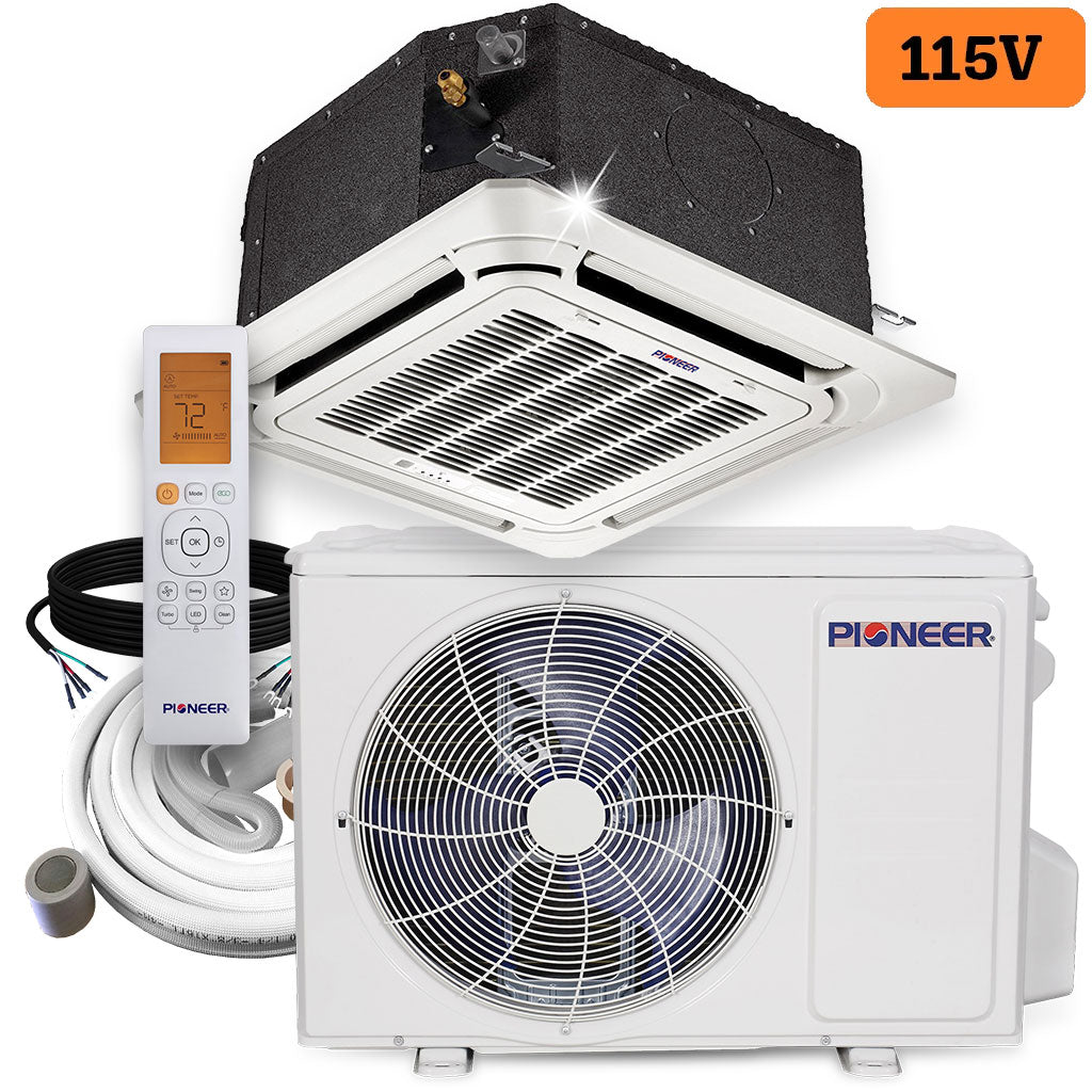
(BTW, I'm well aware of 115V Min-Splits, but I'd like to install a Cassette)
Did you move forward with this installation? I'm looking at the same thing. BTW Pioneer makes a 120V cassette
 
Did you move forward with this installation? I'm looking at the same thing. BTW Pioneer makes a 120V cassette
Not yet... Just picked up the rig on Sep 9th... I still want to do this, but the location for the outside unit is an issue.
I have a 150cc Scooter in a hitch carrier that is taking up the space I had planned to use for the Mini-Split.
(So I'm exploring location options.)

Please share the URL for that 120V unit with Cassette.
 
Last edited:
Heavy iron counts. Go for the heavier transformer or at least the most lbs/$ judged against their VA rating.

A transformer smaller and lighter then the norm for given VA will likely run hotter.
 
The Solaredge has dual E-Type transformers. The Victron is a toroid transformer. Victron wins hands down. We've used the Solaredge at times but only because it's cheaper than the Victron. I don't have exact numbers but the SE is more inefficient. The Victron has a fan and an overload trip etc. The Solaredge has none of the above. For our larger installations, we have toroids custom-wound due to their efficiency. I use them to essentially recreate what's in a Victron AT but with a larger transformer (9.6KVA vs 7.6KVA)..
 
Not yet... Just picked up the rig on Sep 9th... I still want to do this, but the location for the outside unit is an issue.
I have a 150cc Scooter in a hitch carrier that is taking up the space I had planned to use for the Mini-Split.
(So I'm exploring location options.)

Please share the URL for that 120V unit with Cassette.
 
Back
Top