diy solar

diy solar

AWG for Battery ground cable

mani

New Member
Joined
Dec 15, 2020
Messages
24
Hi,

Hope this hasn´t been answered somewhere already but I couldn´t find it.

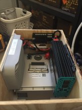
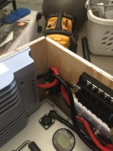
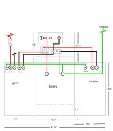
Currently I´m building a 400W solar power system with 200Ah LiFePO battery (12V). I was wondering what gauge wire I should use for grounding the system to chassis? My system is positioned next to one of the wheel wells and I was planning to ground it to one of the struts going accross the wall of the van. The cable is going to have to be around 2-3 ft. long.

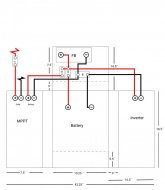
I have attached a diagram of my system. I followed Will Prose video for the 400W system. (The only difference is I´m using a Renogy 700W inverter instead of the one he uses and a 200Ah LiFePO battery instead of sealed lead acid. All other components are the same.)
 

Attachments

  • Battery system.jpg
    Battery system.jpg
    43.1 KB · Views: 35
Typically ground can be smaller than the largest wire (assuming you're not using chassis as current-carrying conductor, the way engine starter does).
Largest wire was sized for continuous current without overheating.
Ground wire is sized to carry fault current long enough to trip breaker/fuse.
Find ground wires sizes in an NEC chart.
 
Last edited:

if I understand this correctly I have to select the size of the fuse closest to my battery? In my case that would be the main fuse (labeled "MF" in my diagram) It´s 70 amps. So my wire should be 10AWG?
 
"Not exceeding 60A" says 10 awg,
"Not exceeding 100A" says 8 awg
 
What ever the positive cables awg, is what to use for negative battery to chassis. The case grounding lugs found on many devices can be smaller.
 
Would it be okay for me to set up the grounding like this? How can I calculate the wire gauges for the inverter and solar charge controller ground wires?
 

Attachments

  • Battery system.jpg
    Battery system.jpg
    49.6 KB · Views: 27
Seems reasonable.
"CB" is a circuit breaker sized for the charge controller?

Each ground wire need to be large enough to clear the breaker/fuse feeding the device.
For inverter, that is the main fuse.
For charge controller, the circuit breaker feed it.
For the solar panels, which may not even have a fuse, use the same size wire as goes to the panels, which should be larger enough to carry 1.56 x Isc of the array.
(If Voc of the array is < 50V I wouldn't worry so much about grounding, but higher voltages could be a safety hazard so frames should be grounded.)
 

so these are the solar panels im using and I was planning on having 4 of them connected in series. (that´s what their customer service recommended) But if I do that then the Voltage will multiply right? So it would be 80V I believe?

Grounding them would be difficult because I have a fiber glass high top so the chassis of the van would be hard to reach.

If I connect them in 2 parallel pairs that are connected in series would that be fine without grounding?
 
Voc = 24.6V, so 4s1p is 100V, 2s2p is 50V

No path to route a ground wire, even though the MC wires go through?

Isc = 5.25A, so either all in series or 2 parallel is a reasonably low current.
Obviously going to MPPT if series is recommended, so either should work.

How much shading? Anything that stands up on the roof? That figures into decisions on how to connect them.
 
Would it be okay for me to set up the grounding like this? How can I calculate the wire gauges for the inverter and solar charge controller ground wires?
While I don't know what the FB is. The wiring looks ok to me. I would redirect the individual wires differing from the graphic diagram. I do recommend a fuse in place of the CB between battery and MPPT. Also, the distance between the battery positive is a bit long to the first fuse. I would have the fuse closer to battery. That is general as I don't know the conditions around the wire from the battery, it may be well protected from fools.
 
I wondered that too, but then ASSuMEd it was "Fuse Box"

I figure a circuit breaker is OK for charge controller if it is non-polar. For dead short it is protected by Main Fuse. Technically, it needs to be able to carry fault currents until the fuse opens, but these things don't have the massive fault currents that grid connected equipment can.

I have seen some people's photos of battery/electronics compartment in an RV, and all the cells had exposed terminals. I would put a cover over them so nothing conductive like a wrench gets dropped on top. I have a string of 8, 6V AGM under my deck and put a corrugated lid over them to keep water and pets off.
 
While I don't know what the FB is.
Yes, FB is fuse box. I know this diagram is not super easy to read. I just made it for myself so I know what all the short cuts are. :D
 
No path to route a ground wire, even though the MC wires go through?
Yea I would probably be able to squeeze another wire through the same inlet box that my solar wires are going through. But if I could do it just by getting a few adapters to do 2s2p and saving myself worrying about grounding I´d rather do that.

There´s nothing on the roof itself that would throw shade really. The only shade might come from and trees or structures around where we prk.

If I change the solar panels to 2s2p would I have to reconsider the gauge of wire to connect them to the MPPT?
 
Two, 5A in parallel is 10A.
You can do the math, but I don't think much power is lost in an RV sized structure at 35 Vmp.
 
FB, fuse block, of course, I wasn't at my best Thursday. Sorry about that.
 
No path to route a ground wire, even though the MC wires go through?
hi again,

i´ve decided to go with 4s1p and grouding the frame since thats how they are set up already. Is there any intructions online i can follow for grounding them?
 
So here are two pictures of how I attached all my panels together. They are all attached together with two aluminum L-struts. I hope its possible to see in the pictures.

I was thinking of drilling a whole into the aluminum part of the frame so that I can attach the ground wire directly using a regular lug and nut/bolt.

Does that seem reasonable?

And to get the AWG of the wire I need it has to be able to carry 13amp at 100V? (since my inline fuse for the panels is 10amp

HAPPY HOLIDAYS!! :)
 

Attachments

  • Solar set up 1.jpeg
    Solar set up 1.jpeg
    83.3 KB · Views: 9
  • Solar set up 2.jpeg
    Solar set up 2.jpeg
    62.5 KB · Views: 9
Aluminum gets native oxide on surface, so a clamped connection alone isn't good electrical contact.
A copper wire under a screw on aluminum will make poor contact, especially with moisture. Probably aluminum wire, oxide removed and corrosion inhibitor would be better.
The UL listed solution is something that bites through oxide into aluminum and has material/plating suitable for wet location with copper.

All something I would worry about for hazardous voltages, but not for Voc < 50V.
Various damage and degradation of PV panels causing leakage to frame is my reason for concern. Been reading PV panel reliability reports.

14 awg carries 15A. I used a spool of bare 10 awg to ground my panels.
 
Looked pretty good.

I think his house battery is 12V. Hardly matters if it has negative tied to chassis; I believe code for fixed application is grounded if > 50V. Preferable to not use chassis as part of the circuit for loads, better to have wire, but if appliances/lights do use chassis as return then you'd need that.

If PV panels in series have Voc above 50V then I'd want grounded, which I think he said he did. Otherwise hardly matters.

It looked like red wire went from fuse box straight to battery positive. Ought to have a main fuse at the battery. Perhaps wire only routes through wood, but if any chance of shorting to chassis, then ground wire ought to be large enough to clear the fuse. I think green ground was a bit small compared to red, but might be sufficient depending on inverter wattage and main fuse size.

I saw wood trim around base of trojan batteries, but no hold-down over the top. Some of my vehicle batteries are held by the base. Needs to be secure, of course.

Good to have electronics in separate compartment from FLA, which give off corrosive and explosive gasses.

Can be useful to have some charging of house bank from alternator when driving, if not much sunlight. He has that on the generator battery but not the new house bank (says PV has been all he needs.)
Thank you this was really helpful!

I just finished my battery system today. (Not connected to anything yet though. Could ou take a look at the pictures and tell me what you think?

All wires are 4AWg except the ones running to the inverter since it came with 6AWG wires I just trimmed those shorter and used them. My plan is to run a ground wire from the negative terminal of the battery to the chassis. (like we discussed earlier)
 

Attachments

  • WhatsApp Image 2021-01-04 at 14.49.33 (1).jpeg
    WhatsApp Image 2021-01-04 at 14.49.33 (1).jpeg
    108.5 KB · Views: 9
  • WhatsApp Image 2021-01-04 at 14.49.33.jpeg
    WhatsApp Image 2021-01-04 at 14.49.33.jpeg
    103.5 KB · Views: 9
  • WhatsApp Image 2021-01-04 at 14.49.32.jpeg
    WhatsApp Image 2021-01-04 at 14.49.32.jpeg
    92.5 KB · Views: 9

diy solar

diy solar
Back
Top