diy solar

diy solar

AWG for Battery ground cable

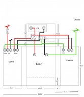
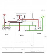
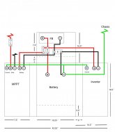
90 degree wire, 6 awg and 4 awg, can carry 105 and 140 amps respectively so long as air can get out of the box.
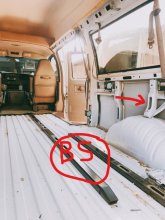
With several heatsink surfaces and fan cooled devices, try to mount in recommended orientation and let air circulate. Maybe holes drilled in the end and screen over them for more ventilation.
 
The charge controller looks like it has a heat sink to be cooled by convection. Mounting it according to manufacturer's instructions should provide better cooling.
The fan cooled ones may be less effected, but may also use convection at low power, only need the fan for higher power.

Insulation on wire is rated according to the temperature it can handle. Common house wiring is rated for 90 degree C can carry current that would cause 60 degrees rise above 30 degree environment. (If used in a hotter location, can't handle as much current.) Some battery cables are rated for 105 degree C. There are a few other types and temperatures.

Cable of bundled wires:


Single conductors with free air circulation can handle more current:

 
@Hedges Okay. Thanks for clarifying that. I will check the manual. I was thinking of leaving the top open. I´m just a little worried about the possibility of water getting in there somehow.
 
Boxes can have baffles to spill falling water but let rising air escape. "3R" enclosures, etc.
I've added a corrugated roof (top of my avatar picture) to keep water from the deck above off the inverters.
 
okay thats interesting. So if I cover the box with a corrugated roof it will let a good amount of heat escape from the sides?
 
Various designs provide venting and deflect water falling from above.
They will present some restriction to airflow, reducing convective cooling.
You just have to estimate what would provide enough venting and enough protection from falling and driven rain.

Convection requires very free airflow paths compared to fan drive. Some of us use an extra PV panel to power a DC fan while the sun shines.


I bought a used box with gasketed door and vent louvers on the sides to hold VFD for a 3-phase pump.
My inverters are supposed to be NEMA 1, but I put a silicone sheet over the breaker and SD card so they are now 3R. The roof (almost a foot above them to allow better air circulation) provides additional protection.
 
For a mobile system, I would seriously consider using WEEB grounding in all the mounting and then a single conductor down to the same place on the chassis your electrical system is grounded. The following is from a grounding resource I am developing for the forum. (I hope to publish it in the next few days)

1609880299064.png
1609880332840.png
1609880210915.png
 
The table says 8AWG as the minimum conductor size, but I wonder if that is necessary for a mobile install.

  • The vehicle is not normally connected to ground so the grounding conductor does not have to try to carry a lightning surge.
  • If the vehicle is plugged into shore power, it becomes grounded.... however the ground wire in the cord to the shore power is probably only 10AWG so I am not sure if an 8AWG does much good.

Current carrying conductor 2 awg, 125A breaker. The 8 awg ground carries sufficient current to trip it rapidly, e.g 5x 125 = 625A or more for milliseconds.

For a mobile system with lower AC output from inverter, and lower amperage from shore power, I could see smaller ground wire being good enough.

Your table is probably for service entrance. If you parked a trailer and had the utility drop a line to it, then the table would be good to follow. Otherwise I would treat as branch circuits. My 20A circuits in 12 awg romex have 12 awg ground (I think.)
 
Would either of these be viable options for grounding my system? I´m trying to avoid putting too many lugs onto my Battery terminal. (i would have 4 lugs on my negative terminal if I do it the way I asked you guys before) I added the first design too.

What do you think of these options?
 

Attachments

  • Battery system ground 1.jpg
    Battery system ground 1.jpg
    49.2 KB · Views: 4
  • Battery system ground 2.jpg
    Battery system ground 2.jpg
    48.4 KB · Views: 4
  • Battery system ground.jpg
    Battery system ground.jpg
    49.6 KB · Views: 4
Would either of these be viable options for grounding my system? I´m trying to avoid putting too many lugs onto my Battery terminal. (i would have 4 lugs on my negative terminal if I do it the way I asked you guys before) I added the first design too.

What do you think of these options?
Minimizing lugs on the battery is a good thing!!!!

Any of them are OK as far as it goes.... but grounding is a system that includes the AC ground. I would need to see the total picture to say what is good or bad. (One thing to watch for is creating ground loops).

BTW: What inverter are you using?
 
What inverter are you using?
I have a 700W Renogy inverter. I thought the AC ground goes to the Inverter and then is transfered via the ground connection on the inverter? (This renogy inverter doesn´t have any high amp connections only two plugs for AC appliances.

What do you mean by a total picture? I posted some pictures of the whole battery system a few posts back if that´s what you mean.
 
This is my best understanding of the grounding for the Renogy 700W inverter
1611175975352.png

Will you only be using the AC sockets or will you hard-wire to an AC distribution box? If so, make sure the distribution box does not have an additional Ground-Neutral Bond.

I would probably use the neg bus bar as the common grounding point. Also, the bond between DC- and chassis does not have to be at the battery terminal. It can be to the bus bar.

1611178737552.png

If the chassis of the inverter and/or chassis of the SCC makes an electrical connection to the vehicle chassis through the mounts, I would be tempted to do it differently in order to avoid ground loops.

1611177678190.png

The idea is to solidify the connection between device chassis and vehicle chassis. If the mount has an adequate bond to chassis, that is all you need. If not adding a wire from the grounding lug to chassis may be needed, but keep it as short as possible. By doing it this way it minimizes ground-loops. However, this depends on ensuring they all make solid connection through the chassis.

BTW: I am assuming none of your DC loads try to use the Vehicle Chassis as the DC return path.
 
Yes I am not using the vehicle chassis for any return paths. I have my whole system (all the parts in the diagram) in a wooden box so there is no way it will make any connections with the chassis.

Refer to the image:
The battery system will be located next to the wheel well and I was planning to connect the ground to that bracket that I have an arrow pointing at. Does that seem good?
 

Attachments

  • InkedWhatsApp Image 2021-01-20 at 15.37.54_LI.jpg
    InkedWhatsApp Image 2021-01-20 at 15.37.54_LI.jpg
    116.5 KB · Views: 4

diy solar

diy solar
Back
Top