diy solar

diy solar

Balancing start voltage, better lower or higher?

cajocars

New Member
Joined
Nov 4, 2022
Messages
324
What open and close starting voltages are you using for passive balance?

How do we determine the optimal voltage? I was thinking that if it’s too high, the cells will have less time to balance and if it’s too low they might balance at a too low state of charge, potentially undoing the top balance

I have 16 280Ah eve cells that were top balanced at 2.65V, a Seplos BMS which resets 100% when one cell reaches 3.45V

My ‘equalization opening voltage’ is currently set to 3.35V
 
3.35V is still close to the flat part of the curve. I think it sould be a bit higher than that. perhaps 3.38V - 3.4V
 
3.35V is still close to the flat part of the curve. I think it sould be a bit higher than that. perhaps 3.38V - 3.4V

The issue I have in mind is that if I increase it to 3.4V for example, a cell is only going to be at 3.4V during the last bit of charging and for very little time

Is balancing supposed to be done while charging or while resting (before/after charging?)?
 
The issue I have in mind is that if I increase it to 3.4V for example, a cell is only going to be at 3.4V during the last bit of charging and for very little time
The amount of time for ballancing is driven by how long the charger stays in the accumulation stage. (How long it stays at the target charge voltage) If you can set it at a few hours you will have time to balance.

Is balancing supposed to be done while charging or while resting (before/after charging?)?
It is generally agreed that the balance should occur at the high end of the charge...beyond that there is a bit of debate and confusion.

Many BMSs give you a choice of Only-while-charging or Never-when-charging. I believe the Never-When-Charging is a bad idea, and given the choice, I would set it to Only-while-charging. However, I would prefer the balance turn-on logic have nothing to do with charging. IMHO, the balance should be on whenever the a cell voltage is above ~3.4V and the differential is greater than ~20mv. Even if charging is not on, if the conditions are met ,the balance circuit should be on.
 
Passive Balancing only burns off voltage from high cells, it does not transfer power like Active Balancing does. Passive is generally useless on large capacity cells as it can only burn off so many millivolts/milliamps "150mA(Max)" from their specs.

With PASSIVE Balancing, IF the cells are well matched for IR through the working voltage range, passive can keep cells balanced to below 20mv but due to the nature of LFP, fo Passive to be reasonably effective, it should start closer to 3.300 Volts per cell and continue to 3.450 which is just above the working voltage range. Remember that Passive only burn off high voltage, therefore as the battery pack charges this is addressed and causes no issues. Also by starting Passive ear;lier on, it takes the "edge" of the high cells making it easier to balance through teh cycle, rather than leaving it to deal with a larger imbalance if started later.

Active Balancing actually moves energy from High Cells to Low Cells and this is usually at a minimum of 1A to 5A depending on active balancer. Too many people start Active Balancing later which results in more work having to be done with a larger imbalance present. This creates a situation where active balancing has to work very hard and this is difficult if the imbalance is high. Again, starting Balancing at 3.300 with Active Balancing, does really keep the cells balanced during charge by addressing any "running" cells (those which gain charge faster) realtime. Again there is NO LOSS With Active Balancing, it is Transfered !

I have been performing assorted usage tests over the past few years with assorted Passive & Active Balancing systems be it within BMS or external. I have testied with 100AH systems to 280AH at all load levels including edge case testing to the extreme ends. The above information provided is a result of years of experience doing this.

Lastly, the Wives Tale to Clobber.
LFP has an Allowable Working Voltage, just like every other battery chemistry in existence. This ALLOWABLE range is from 2.500-3.650 Volts per cell, this is the range where there is no Harm/Damage caused. Below or Above that voltage range WILL cause harm to the cells, No If's And's or But's about it.

FYI: Gross Capacity measurements of a cells include the full "Allowable Range" and therefore if a 280AH cell is tested for gross capacity from 3.650 down to 2.500 it "should" test to between 290AH & 295AH
Net Capacity Tests that are performed by Manufacturers between the 3.000-3.400 volts per cell "working Range".

The LFP Working Voltage Range is what delivers the specified AH rating or call it NET AH for simplicity. That is the FLAT Voltage Curve from 3.000-3.400 Volts per cells with 3.200V being teh Nominal Voltage (and also 50% SOC). Most people will charge to 3.450V per cell which allows the cells to settle post charge input (LFP ALWAYS SETTLES) too 3.425 +/-. Discharge is perfectly safe to 2.800 or even 2.700 Volts per cell but below that can be tricky because the BMS has to recover to a point to allow charge. A deep discharge can easily take the battery down fast when low and you need to have it be able to recover enough to take charge without being cutoff for LVD.

See my Signature for more information inlcuding voltage charts and more.
Hope it helps, Good Luck.

BTW:
I run 3x280AH, 2x174AH (used EV LFP) and 1x10⁵AH in one bank using JKbms with 2A Active Balancing.
Active Balancing starts at 3.300, cells are always within 40mv by the time they reach FLOAT which I have set at 3.400Vpc.
They are ALL under 10mv difference within 60 minutes of float if not less. When cells are colder (<20C/68F) they take a bit longer.

PS: Your EndAmps/TailCurrent for 280AH Battery Pack is 14A. Once the battery is only taking 14A Charge, it is full and ready to go into Float which finishes off the charging & topping.
 
Just thought I would add this separately.
Passive Balancing only burns off High Voltage and as such ist is perfectly acceptable to have running during charge as it is just wasting. As this s used during charge, you are NOT slowing Charge or anything, just knocking the edge off Hi Cells BUT this is wasting it, not transfering it, so "techically" can slow your charging but it is MIllivolts & Milliamps and NOT significant enough to worry over.

Active Balancing MOVES energy and while minimal loss happens it is really not significant as 95% is transferred. Again this is a NO LOSS situation for the pack. It makes No Rational Sense to not use this during charge and keeping the Hi Cells under control through the cycle... it is NOT losing Power, there is No Waste and does NOT SLOW Charging.
 
Balancing below 3.4v can actually result in misbalancing cells. This is due to random inverter loading that will dominate the cell overpotential voltage slump which overwhelms the cells' open circuit voltage comparisons that determines which cells need balancing.

Balancing only above 3.4v pretty much assures balancing only occurs when there is charging current since any moderate inverter discharging load will quickly drop cell voltage below 3.4v, shutting down balancing until cells recover from load current terminal overpotential voltage slump.

BMS's stops balancing current when they periodically make cell voltage measurements, but the BMS does not have control over an inverter/charger current during normal operation. An inverter/charger will apply the same series cell current across all cells, but cell matching gives some overpotential voltage terminal voltage variance due to cell current demanded. In addition, any voltage drop variance in bus bars and terminal connection resistance will affect cell voltage readings by BMS. You don't want this variance in cell overpotential voltage to decide which cells need balancing.

Some BMS's only allow balancing to become active when it detects charging current and disables balancing when discharge current is detected. I don't agree with this method as low current detection is usually not very accurate.
 
Last edited:
In my setup the inverter charges at 50A until the Seplos bms detects that one of the cells reaches
- overvoltage protection (3.45V)
- overvoltage alarm (3.xxV)

If it hits overvoltage protection, then it sets the SoC to 100% and if it hits overvoltage alarm it should reduce the current to 9A
I say it should because most of the times it doesn’t do it, I think it has some delay which means overvoltage protection is met before there is a chance to reduce the current to 10A

I observed that when overvoltage protection occurs the total pack is at about 55.2V (3.45V) and when it stops charging it drops to 53.4V (3.33V)
So there is no balancing after the charge stops

I have to specify I only charge overnight and not by solar

If I reduce overvoltage alarm to a lower value, then the current reduces to 10A too soon and it doesn’t charge to 100%
 
If it hits overvoltage protection, then it sets the SoC to 100% and if it hits overvoltage alarm
Andy's Off-grid-garage video noted this on Seplos BMS.

Requiring you trip cell overvoltage limit to reset SoC Columb counter is just dumb.
 
My inverter doesn’t have a float stage, in other words it only charge at constant current, without the constant voltage part when current would drop off. Whenever the bms say the battery is at 100%, it stops.
 
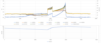
This plot shows the single cells voltage + the deviation on the right hand axis (in mV)

you can see the first part of the charge which is at 50A and carries on until the firs cell hits 3.45V; then the current drops to 10A and carries on until the first cell hits 3.5V. At this point the voltage deviation is about 130mV, but drops to around 5mV as soon as the charge stops
1685983461810.png
is this how it should be?

The voltage deviation stays around 5-6mV during the first part of the discharge (unless there is a heavy load), but it increases to around 25-30mV at about 75% SoC (you can see this in the first half of the plots)
 

diy solar

diy solar
Back
Top