diy solar

diy solar

Batteries in series not charging evenly.

Craig

Watts are Watts!
Staff member
Moderator
Joined
Sep 20, 2019
Messages
2,924
Location
Hollister CA and off the grid in Idaho
So I'm trying to charge 12 cells in series.
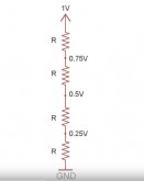
I recently installed a Chargery BMS which lets me know each cells voltage. It seems that the cells starting from the positive end of series decrease in voltage almost in a straight downward line so cell 1 is 2.8 volts cell 2 is 2.75 volts cell 3 2.7 volts on down to 2 volts for cell 12. These numbers are not exact but hopefully you get the Idea. If the cells were randomly different then I would just assume the internal resistance is off but since it is linear I'm wondering if it's something to do with the connectors between batteries? Anybody have any Ideas?
I think that is a sign your load is larger than the series links are rated for...
 
To make a guess, it sounds like your connections (or cells) are fairly high resistance and each cell is acting like a voltage divider resistor set.Vdivide.JPG
 
All wires are same length and cell testing with meter confirms accuracy of bms
I have BYD battery packs 2014 24v 5k the bms wires on the circuit board leading to each battery is different lengths from 6" to 25" odd.

plus it goes 1 + 2- 3- 4 - 5- 6- 7 - 8- it should be 1- 2+ 3+ 4+ etc maybe back in 2014 BYD did not fully understand or stole fake plans
 
So I'm trying to charge 12 cells in series.
I recently installed a Chargery BMS which lets me know each cells voltage. It seems that the cells starting from the positive end of series decrease in voltage almost in a straight downward line so cell 1 is 2.8 volts cell 2 is 2.75 volts cell 3 2.7 volts on down to 2 volts for cell 12. These numbers are not exact but hopefully you get the Idea. If the cells were randomly different then I would just assume the internal resistance is off but since it is linear I'm wondering if it's something to do with the connectors between batteries? Anybody have any Ideas?
Aluminum oxide is a very good insulator. Did you file or wire brush them before attaching your bus bars? I'd suggest changing to copper bus bars.
 
Can you recommend a product?
I like Noalox, a lot. I put it everywhere I have conducting metal touching no matter how big or small. The stuff is almost immortal if its undisturbed. But carbon grease is good too. I doesnt really matter what you use as long as you use SOMETHING on bare-copper-to-bare-copper. If you do tinned-to-tinned the tin/lead coating does the same job and it so soft that when you tighten the two pieces together the tin/lead actually somewhat pressure weld together. You're preventing copper oxidizing and becoming a high resistance contact.
 
Last edited:
So I'm trying to charge 12 cells in series.
I recently installed a Chargery BMS which lets me know each cells voltage. It seems that the cells starting from the positive end of series decrease in voltage almost in a straight downward line so cell 1 is 2.8 volts cell 2 is 2.75 volts cell 3 2.7 volts on down to 2 volts for cell 12. These numbers are not exact but hopefully you get the Idea. If the cells were randomly different then I would just assume the internal resistance is off but since it is linear I'm wondering if it's something to do with the connectors between batteries? Anybody have any Ideas?

Did you ever get to the bottom of this?
 
Did you ever get to the bottom of this?
Not really I am thinking it has something to do with cells not being evenly matched in their capacities and where the energy is in each cell through the voltage range.
some cells seem to have most energy at 2.1 volts and others have it at 2.0 volts. I do not think this is a problem if high and low voltage cutoffs are used but it explains why some are at different voltages than others in the middle voltage ranges.
 
I am seeing a similar (to craig's cells) difference between cells with cell 1 also showing less voltage than cell 4. Just a 3-4mv difference between cells, total in the 10mv range.

I expected the opposite where the first cell would be highest and the last would be the lowest.

Is it a coincidence that the internal resistance of each cell is in the 3-10mv range? There has to be a relationship but i cannot imagine how exactly.

I do not think it has to do with the contact between cell connectors (i am using the carbon connective grease as recommended above, thanks for that!).
 
The batteries may have different actual (as opposed to rated) amp/hr capacities. Being wired in series, they will all get the exact same charging current, but if one has less capacity, it will get to full charge sooner than one with higher capacity, so it's voltage will be higher.
 
Back
Top