detroitmedic
New Member
- Joined
- Dec 3, 2021
- Messages
- 9
Time to bust out the dremel then
It doesn't work like that with 3D printed material to cut out that much material on the shoulder, the outer layers are solid, maybe 3-8 layers thick, but depending on the setup, the internals will be infill, maybe printed at 20-30%, so you lose the strength.Time to bust out the dremel then
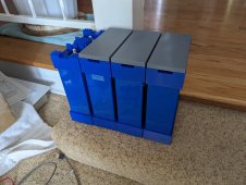
Yeah Sunrise has a bigger printer, I’m printing on a mk3s+, it was a tight fit to get my version to fit.Great design. Won't fit on my Prusa however so I am using the other design where there is a cap on the top and bottom. I have to use metal for my endcaps and will design a box for my JBD BMS to attach to it.
Yeah Sunrise has a bigger printer, I’m printing on a mk3s+, it was a tight fit to get my version to fit.
i Haven’t seen the other design, you got a link to it?


Just have to do supports for the top piece. Took me awhile to figure out the settings to make them easier to remove. Found some settings online that made it easier. In the mean time, I cut the heck out of my hand using a wood chisel when it slipped!Thanks for the link, I hadn’t come across that design, looks easier to print, the lego styles connections are pretty cool.
Not long to go then, until its finished printing, well less than when you started, 3D printing is so slow, looking forwards to seeing the finished unitJust have to do supports for the top piece. Took me awhile to figure out the settings to make them easier to remove. Found some settings online that made it easier. In the mean time, I cut the heck out of my hand using a wood chisel when it slipped!
I like the design in this thread because it looks like it uses a lot less material and I like how the BMS is mounted. Mine will be mounted on the end so you will see the wires going to and from it which isn't as ideal.
Tell me more about the REVO...advantages?My print just got delayed, the print fan gave up in the middle of a print, so i've got to wait until a new fan comes in, Prusa are sending a new one, but i'll also grab a spare locally and fit what ever turns up first and then i'll have a spare, but i guess it's an opportunity to fit the Revo i brought that i haven't gotten around to fitting while i wait for the fan.
i will have to look into that. Figured for everything I do, the stock nozzle would be fine. Definitely, wouldn't want to have to do a live z-adjust for every time I changed the nozzle. Hard enough dialing it in for every one of my sheets.The only advantage for me, is repeatable cold nozzle changes, with no change in Z axis with different nozzle sizes
I get lazy and just end up using the .4 nozzle instead of using a better suited sized nozzle for the job, as its a pain to change.
I got mine already assembled from Prusa, as the waiting time was an extra 6 weeks for a kit, the hotend seems simple enough to install, although still a pain.
I was planning on installing it after printing the battery case, as the printer was dialled in and i didn't feel like pulling it apart
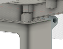
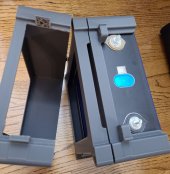
Hi @sunrise , encountered same issue as @jdfrye, terminals are 25.4 mm from stud center to edge. Here's my first attempt to narrow the stool and offset back 20mm. Realigned the screw holes on the lid to match. Widened the opening so the battery can slide in freely. Will print one section tonight to see if it fits. Still thinking about the top cover, whether to make some room under the lid for a small display, outlet, switch, or meter etc. Learning a lot from this project, thank you again for your work on this.So in that case, just play with the parameter won't help as it's outside the range that parameter was designed for . However you can ask your son to adjust the design by doing one of the following
1. narrow the stool the firewall sits on, it doesn't need to be that wide. I think 8-10mm should be enough to accommodate a 3mm screw.
2. move the stool from center to an offset to avoid the terminal
Hope this helps, this is local change of the overall design, you can still reuse most of the design.

oooOOO!! yes! here's to hoping you like what you print.Hi @sunrise , encountered same issue as @jdfrye, terminals are 25.4 mm from stud center to edge. Here's my first attempt to narrow the stool and offset back 20mm. Realigned the screw holes on the lid to match. Widened the opening so the battery can slide in freely. Will print one section tonight to see if it fits.
Looks like you are making great progress. Wondering if you actually need to offset the stool all the way to one end? is it possible to make it 'thinner' + carve the base a little to make room for the stud base?Hi @sunrise , encountered same issue as @jdfrye, terminals are 25.4 mm from stud center to edge. Here's my first attempt to narrow the stool and offset back 20mm. Realigned the screw holes on the lid to match. Widened the opening so the battery can slide in freely. Will print one section tonight to see if it fits. Still thinking about the top cover, whether to make some room under the lid for a small display, outlet, switch, or meter etc. Learning a lot from this project, thank you again for your work on this.
View attachment 88248


