diy solar

diy solar

Battery charging question

If it helps, I have both of the batteries connected to a smart shunt.

Battery #1 (original 200ah with 100a BMS) is currently showing 13.59 and battery #2 with 200a BMW is showing 13.57. Battery #1 voltage is going up faster than battery #2. However, battery #1 has also been charged in the past whereas battery #2 is a new arrival to me and I'm just charging it.
charger + > bus bar + > battery1 +post
...............................................> battery2 +post

charger - > bus bar - > battery1 -post
...............................................> battery2 -post
Ok so I need to move the charger - off of the #1 battery and move it to #2 battery since I guess it's the end of that circuit. Sorry if I've made this confusing --- certainly isn't my intent. I also don't feel like burning my house down LOL
 
I was trying to show battery 1 + and battery 2 + connected to a bus bar for the positive side aka +

So I probably caused the confusion :)

Id put the + battery charger lead on the + of battery 1 and the - charger lead on battery 2's - terminal. This way your charging across them all.

Like @MisterSandals suggested in his post.
 
Update. Because of the victron smart shunt that I have, the charger negative is connected to the shunt "System Minus".
Battery #1 negative is going to shunt "To battery minus".
Battery #2 negative is going to Battery #1 negative
Battery #2 positive is going to Battery #1 positive

Oddly enough, I see the voltage going up on both battries which leads me to believe I might have this wired up ok.

My apologies. I probably should have stated up front that I have that smartshunt.
 
Hook the chargers positive to battery 2's positive.

Hook the chargers negative to inverters side of the shunt if you want to measure whats going into the battery with the shunt.

If you don't care to measure it then put the chargers negative to battery 1's negative.
 
Hook the chargers positive to battery 2's positive.

Hook the chargers negative to inverters side of the shunt if you want to measure whats going into the battery with the shunt.

If you don't care to measure it then put the chargers negative to battery 1's negative.
ok, will do thank you.
 
OHH LORDIE !

OKAY... clarification is needed.
Batteries in Parallel should each be fused.
Paralleling batteries is easiest using Busbars but can be done with wiring. REF to this PDF: https://www.victronenergy.com/upload/documents/Wiring-Unlimited-EN.pdf

When you have batteries in PARALLEL they operate PROPROTIONATELY relative to their capacity. This applies to Charging & Discharging.
Example: 1x 100AH, 1x200AH & 1x300AH in Parallel.
- Charging at 60A would show on the BMS' taking 10A, 20A & 30A respectively and similar when discharging 60A to inverter.
I run 100AH, 175AH & 280AH in parallel and watch this unfold daily ! Also with several systems I have built & installed.
NB: Lessons Learned Dept. You can have different sized packs BUT it get's complicated when it's over 100AH difference... lot of math !

As the individual battery packs fill, the Internal Resistance throttles down the amps they can take, till they reach EndAmps/Tailcurrent at which they will take float & trickle to top off and balance out the last 5% or so. When the 3 packs in the example above reach their Tail, the smaller ones reach it first an will just reduce the amps they take, the larger packs will continue to take I what they can till they reach their tailcurrent.

The BMS' will not allow you to overcharge the battery packs as the BMS will cutoff.
An overly aggressive charge profile CAN & WILL cause cells within the pack to possibly RUN. Meaning that 1 or more cells may hit Hi Volt Disconnect and stop charging. This can handicap the battery & even an entire bank as the Lowest Common Denominator RULES.

Good MODERATE & Conservative profile below that keeps the battery cells within the WORKING VOLTAGE RANGE and not pushing into the Allowable Range which is not for use in general... The Allowable range is just the range in which the cells will not be damaged or harmed, it is not for delivering the AH rating which comes from the Working Range for the cells.

Divide Values X2 for 12V. Multiply X2 for 48V.
Bulk/ Absorb: 27.6 for (3.45vpc) (some call this boost) (absorb for 45 minutes) *never actually runs the full 45mins because of EndAmps
Equalize: OFF
Float 27.5V (3.437vpc)
MIn Volts: 21.2V (2.650vpc)
Max Volts: 28.6V (3.575vpc)
Rebulk Voltage: 25.6 (3.200vpc)
End Amps: (*1) (** Allows for full Saturation at set Float Voltage)
(*1): End Amps is calculated as follows IE: (100AH X 0.05 = 5A or 280AH X 0.05 = 14A.
EndAmps = TailCurrent. This is the same thing, terminology varies.
Coulumbic Efficiency / Battery Status Meter Efficiency for LFP = 99%.
This get's the bank charged to full with high amps (Constant Current - Constant Voltage) and then float (Constant Voltage - Variable Current) tops off so the cells are at 3.47Vpc.
* Do Not forget to adjust for Voltage Offsets between Actual Voltage @ Battery Terminal & at Solar Controller.
Very Special NOTE: Floating & Saturating to 3.437vpc, accounts for the Voltage Settling post Charge of any kind which actually brings the cells to just below 3.400Vpc.
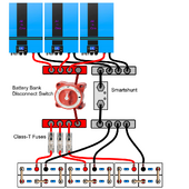
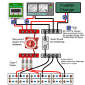
Two -A-Typical generic diagrams below for ref.
1704027858800.pngParallel System-setup PNG.png
 
OHH LORDIE !

OKAY... clarification is needed.
Batteries in Parallel should each be fused.
Paralleling batteries is easiest using Busbars but can be done with wiring. REF to this PDF: https://www.victronenergy.com/upload/documents/Wiring-Unlimited-EN.pdf

When you have batteries in PARALLEL they operate PROPROTIONATELY relative to their capacity. This applies to Charging & Discharging.
Example: 1x 100AH, 1x200AH & 1x300AH in Parallel.
- Charging at 60A would show on the BMS' taking 10A, 20A & 30A respectively and similar when discharging 60A to inverter.
I run 100AH, 175AH & 280AH in parallel and watch this unfold daily ! Also with several systems I have built & installed.
NB: Lessons Learned Dept. You can have different sized packs BUT it get's complicated when it's over 100AH difference... lot of math !

As the individual battery packs fill, the Internal Resistance throttles down the amps they can take, till they reach EndAmps/Tailcurrent at which they will take float & trickle to top off and balance out the last 5% or so. When the 3 packs in the example above reach their Tail, the smaller ones reach it first an will just reduce the amps they take, the larger packs will continue to take I what they can till they reach their tailcurrent.

The BMS' will not allow you to overcharge the battery packs as the BMS will cutoff.
An overly aggressive charge profile CAN & WILL cause cells within the pack to possibly RUN. Meaning that 1 or more cells may hit Hi Volt Disconnect and stop charging. This can handicap the battery & even an entire bank as the Lowest Common Denominator RULES.

Good MODERATE & Conservative profile below that keeps the battery cells within the WORKING VOLTAGE RANGE and not pushing into the Allowable Range which is not for use in general... The Allowable range is just the range in which the cells will not be damaged or harmed, it is not for delivering the AH rating which comes from the Working Range for the cells.

Divide Values X2 for 12V. Multiply X2 for 48V.
Bulk/ Absorb: 27.6 for (3.45vpc) (some call this boost) (absorb for 45 minutes) *never actually runs the full 45mins because of EndAmps
Equalize: OFF
Float 27.5V (3.437vpc)
MIn Volts: 21.2V (2.650vpc)
Max Volts: 28.6V (3.575vpc)
Rebulk Voltage: 25.6 (3.200vpc)
End Amps: (*1) (** Allows for full Saturation at set Float Voltage)
(*1): End Amps is calculated as follows IE: (100AH X 0.05 = 5A or 280AH X 0.05 = 14A.
EndAmps = TailCurrent. This is the same thing, terminology varies.
Coulumbic Efficiency / Battery Status Meter Efficiency for LFP = 99%.
This get's the bank charged to full with high amps (Constant Current - Constant Voltage) and then float (Constant Voltage - Variable Current) tops off so the cells are at 3.47Vpc.
* Do Not forget to adjust for Voltage Offsets between Actual Voltage @ Battery Terminal & at Solar Controller.
Very Special NOTE: Floating & Saturating to 3.437vpc, accounts for the Voltage Settling post Charge of any kind which actually brings the cells to just below 3.400Vpc.
Two -A-Typical generic diagrams below for ref.
View attachment 186005View attachment 186004
Thank you for that detailed info. It's going to take me a while to learn all of this :)
 
Thank you for that detailed info. It's going to take me a while to learn all of this :)
You're Welcome.
The reality is, it takes a Minimum of 6 months of concentrated study or 1 Year for casual study to wrap ones head around it. Also the hardest thing a lot of people hit, is they look at things and think in AC Terms which do not really apply to DC gear... a LOT of Electricans (AC Systems) have serious issues with understanding DC.

Fortunately, this is a Good Site with a lot of us that Live the Life & Do the Life, several of us are actually in the industry as well. You just need a lot of time & patience and use common sense, ask questions (there are no dumb ones, except for the one not asked) and NEVER EVER RUSH or be in a Haste ! Take your time & absorb it.
 
Back
Top