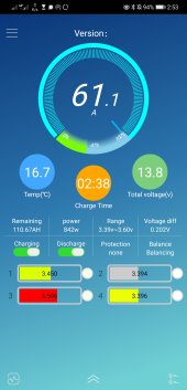
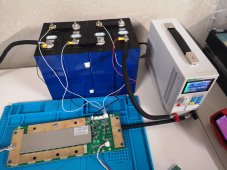
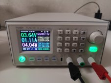
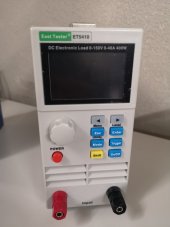
You did not state the amount of load is being applied but I assume you are loading with a sinewave inverter. Based on the loaded cell voltage slump with a 272 AH cell, I would guess you are putting about 40 amp load on battery.
The BMS is likely averaging any battery voltage 120 Hz ripple from the 120 Hz ripple load current.
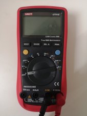
The DVM might be averaging the voltage or if it is a true RMS meter it might be true rms of the rippling DC voltage, or just does not like the 120 Hz ripple voltage riding on top of the DC voltage.
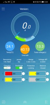
With no load on inverter, the DC current is just the idle current of inverter which is primarily the power required to run the drivers which is supplied by a high frequency DC to DC converter so the DC current is almost constant smooth DC with little to no 120 Hz ripple current.
When you load a sinewave inverter the 120 Hz ripple current dominates the inverter current and the readings depend on how the DC voltmeter reacts to the 120 Hz ripple voltage riding on the batteries due to battery impedance and the 120 Hz ripple current from inverter. The greater the cell impedance (poorer cell condition) the more ripple voltage there will be on cell due to its internal impedance.
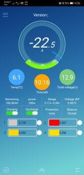
The delta between lowest and highest cell in this voltage range is not as important as the delta between rested and loaded per cell. It will indicate the matching between cells (not to be confused as SOC balance). You should have cell load current of 0.2 to 0.4 C(A) current rate to get good test on cell matching. That would be 50 to 100 amps for a 272 AH cell.
On a per cell basis, your data rearranged:
 Conclusions:
1) no load voltage difference between meters is only 0.3% (
no 120 Hz ripple current present at no load)
2) One of the meters doesn't like the 120 Hz ripple voltage present on cells under load. Based on slump voltage I would guess DVM doesn't like the 120 Hz ripple voltage.
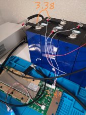
3) The BMS reading of first cell voltage slump with load is disturbing. It shows higher cell voltage slump under load. Check cell terminal connections. It could also because of terminal connection and you probed battery with DVM directly on battery terminals not subjecting the DVM to the bus bar connection issue. DVM is showing higher voltage reading.
4) The first cell voltage slump does not show up on DVM reading. This might be due to the 120 Hz ripple voltage effect on DVM where DVM is measuring close to peak of ripple voltage. This is typical of a cheaper DVM.
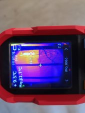
The big question is the first voltage cell with greater BMS reading voltage slump under load also the same cell you indicated has greater temperature rise? Having greater internal impedance, with greater terminal voltage slump with load current would cause cell to heat up more. This would indicate a cell matching issue with first voltage cell being in poorer condition than other three cells.
A greater cell internal impedance will also affect charging voltage rise on cell, causing it show greater cell voltage under charge current.
Hopefully all you have is a bad bus bar connection.