diy solar

diy solar

Battery wire size?

@CJMainer - to help this discussion along, could you estimate the overall length of wiring you plan? For example, how long will the + and - wires be? In my case I have the battery -> buss-bars and the other equipment has their own wiring to the bus-bar. So i'm measuring from the battery to the bussbar.


OK, I'll byte. Seem like a very negative reaction to my post. Assuming I'm right, what exactly do you-all find 'untrue' about my post?


For example - this chart is off on 4/0 (too low for short distance) because it doesn't mention chassis amps. This is why I posted a chart that includes the chassis amps.

If I may - gently - suggest that we flush out specifics to help the poster because a lot of these discussions are vague.

My personal goal is to share what worked for me, not push anyone into anything or make general statements about all wiring. :)
It was a negative reaction. Not to your post in particular, but the whole thread. There is a lot of half-baked information that is of little use to the OP.

I do question your claim that the number of strands has a huge effect on wire temperature. The chart I posted claims just the opposite. Strand counts of 1, 7, and 19 all produce the same ampacity.
To be clear - I'm talking about 'Class K' - thousands? of very small strands.
And looks like I'm wrong on my understanding as some googling today insists it makes no difference - its the total cross-section size of copper that matters - solid or stranded. But I also found that I'm not alone in this understanding, so maybe it's one of those urban legends.

Note: Here's a detailed comment from - https://lugsdirect.com/GuideToFlexFlexibleFineStrandedWireCableMechanicalLugsFAQ.html -
And down lower in Section #5, point 2.... it says
------------------------
2. The larger physical diameter of the fine stranded wire creates a higher wire to air cooling factor versus a smaller diameter coarse stranded wire due to increased surface area.
------------------------

So maybe it's something like this that lead to the urban legend that cooler = more amps?

One big difference with fine-strand is that the wire is easy to bend / flexible and at 4/0 AWG this can be a plus :)
 
Last edited:
To be clear - I'm talking about 'Class K' - thousands? of very small strands.
And looks like I'm wrong on my understanding as some googling today insists it makes no difference - its the total cross-section size of copper that matters - solid or stranded. But I also found that I'm not alone in this understanding, so maybe it's one of those urban legends.

Note: Here's a detailed comment from - https://lugsdirect.com/GuideToFlexFlexibleFineStrandedWireCableMechanicalLugsFAQ.html -
And down lower in Section #5, point 2.... it says
------------------------
2. The larger physical diameter of the fine stranded wire creates a higher wire to air cooling factor versus a smaller diameter coarse stranded wire due to increased surface area.
------------------------

So maybe it's something like this that lead to the urban legend that cooler = more amps?

One big difference with fine-strand is that the wire is easy to bend / flexible and at 4/0 AWG this can be a plus :)
Yes, I use the same stuff and like it's flexibility. Reminds me of a girl I once dated. These guys seem to have reasonable prices. https://www.batterycablesusa.com/

I've used quite a bit of Litz wire. Litz wire is many fine strands as well, but each strand is individually insulated. It is good for switching power supplies that run at higher frequencies.

I didn't realize until recently that 60Hz power lines are affected by skin effect too. Maybe DC transmission of gobs of power is a good idea. I heard a company I once worked for is stringing up some very large DC lines across China.
 
To be clear - I'm talking about 'Class K' - thousands? of very small strands.
And looks like I'm wrong on my understanding as some googling today insists it makes no difference - its the total cross-section size of copper that matters - solid or stranded. But I also found that I'm not alone in this understanding, so maybe it's one of those urban legends.

Note: Here's a detailed comment from - https://lugsdirect.com/GuideToFlexFlexibleFineStrandedWireCableMechanicalLugsFAQ.html -
And down lower in Section #5, point 2.... it says
------------------------
2. The larger physical diameter of the fine stranded wire creates a higher wire to air cooling factor versus a smaller diameter coarse stranded wire due to increased surface area.
------------------------

So maybe it's something like this that lead to the urban legend that cooler = more amps?

One big difference with fine-strand is that the wire is easy to bend / flexible and at 4/0 AWG this can be a plus :)
Alrighty then, I guess we both learned something. Thanks for clarifying. (y)
 
That chart is for "welding applications", intermittent use, not hours at a time. Look for "ampacity charts", the numbers will be much lower.
@OffGridInTheCity @Roswell Bob

I am an armature just trying to wrap my head around all of this and I read this thread last night which really got me thinking as I am setting up my own battery bank and I had already purchased and made cables using welding wire and my previous assumption that it carries higher capacity.

System Config: 8s 24v 280ah pack with jbd 150 bms and a 3000watt inverter. The welding cable I purchased is 1awg from temco which has a max rating of 240 amps to use between cells and to busbar and then inverter. I will rarely max it out but want to be safe.

Anyway, I was a bit concerned after reading this thread that I may have undersized the cable and may have to remake some new ones so I called the manufacturer, Temco to inquire about this and their response was that it does not matter the use (welding or not) that the max amperage stated (240a) is correct for continuous use. I further inquired regarding cross section length and wire strand thickness and why their wire was so much higher compared to other charts. They responded by saying that because their are so many factors in manufacturing the wire that their isn't a standard chart that can be used across all wire and that you should always only use the manufactures chart.

Just thought I'd share what I learned but regardless, once installed I think my best course of action would be to test the system at max load and see how hot the wires get.

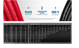
Just in case you wanna see Temco's Chart and Wire Info:
 
Last edited:
@OffGridInTheCity @Roswell Bob

I am an armature just trying to wrap my head around all of this and I read this thread last night which really got me thinking as I am setting up my own battery bank and I had already purchased and made cables using welding wire and my previous assumption that it carries higher capacity.

System Config: 8s 24v 280ah pack with jbd 150 bms and a 3000watt inverter. The welding cable I purchased is 1awg from temco which has a max rating of 240 amps to use between cells and to busbar and then inverter. I will rarely max it out but want to be safe.

Anyway, I was a bit concerned after reading this thread that I may have undersized the cable and may have to remake some new ones so I called the manufacturer, Temco to inquire about this and their response was that it does not matter the use (welding or not) that the max amperage stated (240a) is correct regardless of use. I further inquired regarding cross section length and wire strand thickness and why their wire was so much higher compared to other charts. They responded by saying that because their are so many factors in manufacturing the wire that their isn't a standard chart that can be used across all wire and that you should always only use the manufactures chart.

Just thought I'd share what I learned but regardless, once installed I think my best course of action would be to test the system at max load and see how hot the wires get.
"I am an armature just trying to wrap my head around all of this..." :ROFLMAO: There it is THE PhUnnY-O-the Day Award.

Thanks for sharing. You are the first person I know of who actually got someone to answer the phone at TEMCo.

So I did some checking on 2 awg welding cable and TEMCo & WindyNation are rated 205 amps, while Southwire rates their 2 awg welding cable at 190 amps (no temperature data was given for these products).

Cooner rated one of their 2 awg cables: 215 amps at 105°C, and 293 amps at 200°C.
Some other types of 2 awg are rated at 95 to 190 amps.

Not all 2 awg cables are created equal.
Its also related to the length. My chassis amps chart - https://www.powerstream.com/Wire_Size.htm - shows 2AWG at 181a. So if they said 205a then the next question is how long is the wire - I would guess we're talking very short as in 1ft kind of thing.

This is why I suggested (above) it's OK to try 2awg (thinking - if the wire is short enough) but that I know from personal experience that 4/0 AWG will work up to 10ft.

I do look forward to hearing what you choose and how it works for you! That's really the bottom line - does it work safely for your max load and situation :)
 
Its also related to the length. My chassis amps chart - https://www.powerstream.com/Wire_Size.htm - shows 2AWG at 181a. So if they said 205a then the next question is how long is the wire - I would guess we're talking very short as in 1ft kind of thing.
Numbers off their sites:
EDIT: TEMCo link fixed, all numbers still remain the same.
temcoindustrial.com/temco-wc0132-welding-cable-2-awg-20-ft-red/
www.windynation.com/Welding-Battery-Cable/Windy-Nation-Inc/2-0-AWG-WELDING-CABLE-WIRE-RED-BLACK-GAUGE-COPPER-WIRE-BATTERY-SOLAR-LEADS/-/690?p=YzE9MjM=
www.cerrowire.com/products/resources/tables-calculators/ampacity-charts/
www.coonerwire.com/amp-chart/

industrial.southwire.com/en/tile/10/spec/70305/
 
Last edited:
Ah - the top link goes to 2/0 AWG (not 2AWG). 2/0 is quite a bit thicker than 2. Yes - 2/0 AWG should handle up to 283a chassis amps :) So yes this should work up to 10 or 15ft kind of thing.
 
@OffGridInTheCity
All I could find was a temperature range shown below -50c to105c as well as the ampacity for welding cable length below and for welding distance. I doubt that would translate for continuous use lengths.
weldingcable.PNG
 
@OffGridInTheCity @Roswell Bob @WYtreasure

On a side note related to this, I am trying to figure out what breaker size I would use between battery/bms and bus bar. My bms is rated for 150amps continuous. I am using a 3000watt inverter which I will use rarely but the manual for that calls for 210amp breaker which they calculate by 168continuous *1.25=210. Where I am unsure is that if my bms can only handle 150 continuous amps and the wire is sized much higher should I rate the breaker to protect the bms somehwere closer to 150 and well under the wire max? Or bump everything up to the 210 which is what the minimum the inverter calls for? both would still be under the 240 wire rating.
 
Last edited:
@OffGridInTheCity
All I could find was a temperature range shown below -50c to105c as well as the ampacity for welding cable length below and for welding distance. I doubt that would translate for continuous use lengths.
View attachment 85306
As someone above pointed out - welding is short duration - e.g. minutes. Solar/Powerwall/Inverter is 24hrs a day - e.g. heat can build up during warm afternoons.

For example, I have 4awg welding wire between my Midnite Classic Charge controllers and the main bus. Its about 10-15ft. These run 80a thru the day at full PV power but are in conduit. I have temp sensors on them and in summer with ambient of 80F they get near 60C/140F. In winter at 60F ambient they get 45C/113F. No way would 4awg carry continuous 200a for 50ft on a warm afternoon as shown above for welding!

As I've mentioned, I use the chassis amps from this chart https://www.powerstream.com/Wire_Size.htm as a guide for short distances (<10F) and it's worked out in practice for me.

1ft vs 5ft vs 10ft really make a difference. For example, I had 0.5"-1" of 4awg (yes - <1 inch) between the main bus and the shunt to the battery for a while after a major upgrade. This reached 200a occasionally and didn't seem to bother it / did not get hot. It bothered me and I changed it to 4/0.

As another example, the Reliance Pro/Tran MTS uses 10awg from the incoming 240v@50a plug to the buss for the switches. Its about 5" long. That 50a on 10awg!!! This was confirmed with the company to be UL compliant. Crazy to connect 6AWG to 10awg. This bothered me too and I changed it to 6awg.

I'm just saying that in my experience 'very short' (inch or 2) and short (couple of feet) and longer (50, 100 feet) seem to be fundamentally different situations.
 
Last edited:
As someone above pointed out - welding is short duration - e.g. minutes. Solar/Powerwall/Inverter is 24hrs a day - e.g. heat can build up during warm afternoons.

For example, I have 4awg welding wire between my Midnite Classic Charge controllers and the main bus. Its about 10-15ft. These run 80a thru the day at full PV power but are in conduit. I have temp sensors on them and in summer with ambient of 80F they get near 60C/140F. In winter at 60F ambient they get 45C/113F. No way would 4awg carry continuous 200a for 50ft on a warm afternoon as shown above for welding!

As I've mentioned, I use the chassis amps from this chart https://www.powerstream.com/Wire_Size.htm as a guide for short distances (<10F) and it's worked out in practice for me.

1ft vs 5ft vs 10ft really make a difference. For example, I had 0.5"-1" of 4awg (yes - <1 inch) between the main bus and the shunt to the battery for a while after a major upgrade. This reached 200a occasionally and didn't seem to bother it / did not get hot. It bothered me and I changed it to 4/0.

As another example, the Reliance Pro/Tran MTS uses 10awg from the incoming 240v@50a plug to the buss for the switches. Its about 5" long. That 50a on 10awg!!! This was confirmed with the company to be UL compliant. Crazy to connect 6AWG to 10awg. This bothered me too and I changed it to 6awg.

I'm just saying that in my experience 'very short' (inch or 2) and short (couple of feet) and longer (50, 100 feet) seem to be fundamentally different situations.
Thanks for the response. My application for the 1 awg is between battery cells which is approximate 4 or 5 inches in length. It might be fine but I think I will do some testing to be sure and if it gets too warm jump to larger wire. Thanks again, any thoughts on the breaker question I mentioned above?
 
Thanks for the response. My application for the 1 awg is between battery cells which is approximate 4 or 5 inches in length. It might be fine but I think I will do some testing to be sure and if it gets too warm jump to larger wire. Thanks again, any thoughts on the breaker question I mentioned above?
Everything (maybe) you ever wanted to know about wires, fuses, breakers. If it's not in this thread it's in FilterGuy's signature.

 
Thanks for the response. My application for the 1 awg is between battery cells which is approximate 4 or 5 inches in length. It might be fine but I think I will do some testing to be sure and if it gets too warm jump to larger wire. Thanks again, any thoughts on the breaker question I mentioned above?
@OffGridInTheCity @Roswell Bob @WYtreasure

On a side note related to this, I am trying to figure out what breaker size I would use between battery/bms and bus bar. My bms is rated for 150amps continuous. I am using a 3000watt inverter which I will use rarely but the manual for that calls for 210amp breaker which they calculate by 168continuous *1.25=210. Where I am unsure is that if my bms can only handle 150 continuous amps and the wire is sized much higher should I rate the breaker to protect the bms somehwere closer to
150 and well under the wire max? Or bump everything up to the 210 which is what the minimum the inverter calls for? both would still be under the 240 wire rating.
Remember that a breaker primary job is to 'protect the wire'! so it follows that you can use a smaller breaker than the amps the wire can handle but you cannot use a larger breaker than the wire can handle.

Loads (devices) are usually responsible for their own protections - e.g. the BMS has it's own 150a limit, an inverter will have breakers of fuses inside, etc.

In you're specific case - if you have 200a wire (does not get hot) but want to make sure your BMS does not trip, then a 125a or 150a breaker is OK. If you just want to protect the 200a wire and let the device (BMS) take care of itself - then 200a breaker is OK.

-----------------------------
Breakers are a whole other subject. What I think of as a 'normal' breaker will pop (pretty much) at the rated amps within a few seconds. For example the Midnite DC breakers 125a, 175a, 250a such as these https://www.midnitesolar.com/products.php?menuItem=products&productCat_ID=8&productCatName=Mini DC Disconnect trip as you might expect. I have 2 x of the 250a breakers and I know they trip quickly because mine tripped once :)

But others have a looooong trip time as illustrated by @DavidPoz in this youtube. Breakers >100a get into a different relm than ordinary 15a, 20a, 50a ranges.
 
Last edited:
@WYtreasure Thanks for the link. Lots of great info.
@OffGridInTheCity Thanks for the response, helpful to understand and look at it that way.

If I decided I should upgrade my battery interconnect wires after testing (which seems likely) would their be any concerns doubling them up with another wire or grounding strap or would that cause potential issues?

Context: I previously purchased these grounding straps to use a flexible bus bars between the battery cells but then went with the 1awg route instead (I know, lots of costly mistakes and learning here)....

They are rated for 150amps on their website but I called the manufacture and asked about continuous ampacity and they said they would be rated for 120 continuous based on their cross section width. I know I'd have to heat shrink them to use them but if I do need to upgrade would combining those work without presenting a safety issue?
 
@WYtreasure Thanks for the link. Lots of great info.
@OffGridInTheCity Thanks for the response, helpful to understand and look at it that way.

If I decided I should upgrade my battery interconnect wires after testing (which seems likely) would their be any concerns doubling them up with another wire or grounding strap or would that cause potential issues?
I know I'd have to heat shrink them to use them but if I do need to upgrade would combining those work without presenting a safety issue?
I know where to find answers, that does not mean I understand them. I do know it matters which connection goes on the battery first, what materials should be used, and that it's all torqued down real nice.

Don't use your own finger to do the heat test on terminal posts. ?

 
Back
Top