diy solar

diy solar

BMS common port vs seperate port

sure, but there still can be a malfunction and then it is better if some simple relay can just shut off that 200A current

I'm really not interested in debating the merits of various strategies ... I was just trying to say there are various ways and various types of relays .... everyone has to find their own strategy.
 
what I also really hate with these chinese BMS - most of them have no mounting holes. How difficult is that to just make two "ears" on the sides so the customer can screw that down somewhere? Chinese stuff mostly works but just lacks basic details.
 
On my JK-BMS, I took out 3 of the screws that hold it together, I drilled the holed all the way through and tapped them the rest of the way. Then I got longer 3 mm screws to bolt through the mounting plate and into the BMS. I could easily tell the back of the BMS was not very flat, so I used a few varying layers of thermal conductive tape to act as shims so it sat flat and still carried the internal heat into the large aluminum plat that I bolted it to. I also added a heat sink on the BMS over the MOSFETs with the thermal tape. At the current I run, I probably didn't need it, but in testing at 80 amps, I did feel it get a little warm. Now it runs dead cold.

I am a firm believer in making it "fail safe". If something is going to fail, it should do it in a safe manner. The BMS alone should provide decent protection if another device goes wrong. But if it is the BMS that fails, what is the safety? I have a 100 amp fuse on each string of batteries, and then a 225 amp Class "T" fuse on the main feed out to the inverter. When I do add the DC solar charge controller, it will also have it's own dedicated 60 amp fuse to the battery buss. The inverter and charger settings should always stay well within safe limits of the battery voltage, but if they don't, then the BMS units will disconnect. If the current exceeds safe limits, the BMS units should also shut down, but if they don't, then a fuse is still there to stop it.

With all of the news about the Chevy Bolt battery fires, I am also going to add a smoke detector inside of each battery cabinet. At even a hint of smoke, it will set off the siren. Both my battery bank cabinets are on wheels. If anything goes wrong, I just yank the DC plug and roll it out to the street. I store my weld next to them, so I have a pair of heavy welding gloves right there as well.
 
The issue you run into with a separate port BMS is when the charge controller is supplying a lot of power, and the inverter is pulling a lot of power. All of that power is going through both sets of MOSFETs in the BMS and causes it to heat up. With a common port, the Charge controller is directly powering the inverter, and only the difference in current is either going in or out of the BMS. You could have 100 amps coming from the charge controller, and the inverter pulling 90 amps, and the BMS only sees 10 amps.
Maybe there should be a separate forum just for RV's, campers and caravans etc. There is a lot of chat here talking about amperages WAY higher than I would ever want or need, 100 amps from CC! in an RV?, I don't think so Tim. So anyways my system seems to be chuffing along nicely, haven't had any issues in the last 12 months.
In relation to the discussion about LiFePO4 cells holding up in rough conditions I would just say this, there are currently (it appears) about half a millions RV's of different types coming straight from the factory with lithium batteries, bashing their way around the Australian Outback. Try 600 kilometres of bad washboard corrugations at about 80 Klms an hour! (not my idea of fun). That will shake the sh#t out of anything, and often destroys suspensions and tyres, haven't heard a peep from anyone about battery damage to date.

Safe travels everyone.

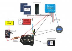
My system:
LiFePO4 & BMS connections + (3 way switch).jpg
 
Maybe there should be a separate forum just for RV's, campers and caravans etc. There is a lot of chat here talking about amperages WAY higher than I would ever want or need, 100 amps from CC! in an RV?, I don't think so Tim. So anyways my system seems to be chuffing along nicely, haven't had any issues in the last 12 months.
In relation to the discussion about LiFePO4 cells holding up in rough conditions I would just say this, there are currently (it appears) about half a millions RV's of different types coming straight from the factory with lithium batteries, bashing their way around the Australian Outback. Try 600 kilometres of bad washboard corrugations at about 80 Klms an hour! (not my idea of fun). That will shake the sh#t out of anything, and often destroys suspensions and tyres, haven't heard a peep from anyone about battery damage to date.

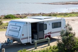
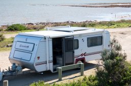
I have dual Victron MPPT 100/50 solar charge controllers in my RV trailer. This last week I was close to 80% output of the two combined. Close to 100 amps, but not quite.
 
Must be a whopper, how many panels? Specs?
I don't have the room, and don't want to add any more weight, (just updated suspension.
 

Attachments

  • Panels on roof.jpg
    Panels on roof.jpg
    364.4 KB · Views: 9
Must be a whopper, how many panels? Specs?
I don't have the room and don't want to increase weight, just updating suspension to higher ATM.

I built a rig to setup new (parrallel bearing stub axles, worked a treat 8/10ths of a millimetre after tacking, going to welder for final welds next week.

Happy camper.
Panels on roof.jpg
 
The correct way of doing it would be to tell the charger(s) to switch off when one cell goes overvoltage and same for the load on undervoltage. usually MPPTs will detect the total voltage but not per cell voltage, same for inverters. The consumer stuff just lacks the right ports! BMS should have charge on/off and load on/off signals and both chargers and inverter should have a simple logic level input to be controlled that way.

Manufacturers make us suck and forcing into DIY solutions, by not providing the right interfaces out of the box.
 
Having read all the above discussions and looked at my setup, which includes an All-In-One SCC/Inverter, I've realized something. There is no way to isolate the charging versus inverter load current with an All-In-One, short of buying a separate inverter. There is only one connection between the All-In-One and the battery which serves both for charging and discharging through the inverter. Any BMS that is used in this situation is going to disconnect the battery from the All-In-One.

DC and separate Inverter could be isolated, but having to buy a separate inverter defeats the purpose of the All-In-One.
So, I'm left with the conclusion that I need to run my batteries within a safe SOC zone. Now that safe zone could be made broader I there was a BMS that aggressively balanced cells. Is anyone aware of which BMS is the best at balancing cells quickly?

Second, it seems from the discussion that using a relay to cut charging is not good for the SCC. Having observed my SCC's operation that makes sense. It does not just suddenly jump from absorption to float charging but rather ramps down over about a minute. This can be seen by observing the current and voltage as this change occurs.
The best practice is to use a remote relay or switch to shut down the inverter if the battery is disconnected by the BMS.

It is easily done on something like a GW, Will showed how to wire in a remote switch on an All In One. Simply a case of making it automated. For example, if using a shunt trip breaker with a Batrium, the Batrium relay can be used to also shut off the inverter remotely. This is the beauty of using a BMS such as the Batrium, you can remotely trigger relays, breakers and switches.

Why would this be done? If PV is still connected and current is flowing to the AIO, the inverter could continue to function and possibly be damaged if PV input is low and load is high at time of BMS disconnect. Many AIO's however, do have a setting if Battery is not available to automatically switch to grid but the switch for the unit may have to be switched on. This is fine for load reduction systems or those with a grid connection. In a totally off grid system, it might be wise to have the system fully shut down if a BMS disconnect occurs.
 
Maybe there should be a separate forum just for RV's, campers and caravans etc. There is a lot of chat here talking about amperages WAY higher than I would ever want or need, 100 amps from CC! in an RV?, I don't think so Tim. So anyways my system seems to be chuffing along nicely, haven't had any issues in the last 12 months.
In relation to the discussion about LiFePO4 cells holding up in rough conditions I would just say this, there are currently (it appears) about half a millions RV's of different types coming straight from the factory with lithium batteries, bashing their way around the Australian Outback. Try 600 kilometres of bad washboard corrugations at about 80 Klms an hour! (not my idea of fun). That will shake the sh#t out of anything, and often destroys suspensions and tyres, haven't heard a peep from anyone about battery damage to date.

Safe travels everyone.

My system:
View attachment 66804
Wondering : Should’nt the shunt be after the the BMS ? Building my caravan battery now and adding a Victron Smart Shunt.
 
the shunt provides pretty important information

shunt also consumes power

leaving shunt hard wired will prevent disconnect reset of readout

it could also damage battery if left unattended indefinitely

random thoughts

each system is a collection of trade offs ??
 
the shunt provides pretty important information

shunt also consumes power

leaving shunt hard wired will prevent disconnect reset of readout

it could also damage battery if left unattended indefinitely

random thoughts

each system is a collection of trade offs ??
So , shunt goes after BMS ? For this build I am using a non smart Daly BMS because I have a few surplus to requirement.
 
So , shunt goes after BMS ? For this build I am using a non smart Daly BMS because I have a few surplus to requirement.
For my main build, I put the Victron SmartShunt before the BMS because I don't want the shunt to lose power and lose all its info. It only draws 10mA, and it has a fuse that would cut it off if something goes wrong.

For the build I'm doing for someone else, I've got a 2P4S two-battery bank, each with their own BMS. I'm using one SmartShunt to monitor the bank, so it is after the two BMS's.
As I see it , if practicable ( i.e. drop - in replacements where the BMS is not accessible ) , the SmartShunt should go between the battery and BMS , i.e. most negative point in the cct as there is a small pd across the BMS when on. I see the shunt has a +ve supply feed as well to operate and will thus retain data. Thanks for that and it is clear now.
 
Hello guys, I have a question: I don't know if I have to change my Daly BMS 16s Common port with one jbd separate with 2 relay. For now my off-grid sistem is composed of an hybrid inverter 48v 5kw that is connect to my bms daly 48v common port. Now I would like to add an eolic generator that will charge battery. Do you think i have to change bms or can i connect? Thanks, guys.
 
You should be able to connect it to the same output port of the BMS as the inverter. Have a separate fuse and disconnect switch though. If the generator does over charge the battery, the BMS will disconnect to protect the battery. The only problem would be what happens at the wind generator output if it becomes unloaded. This is something you will need to test. It should have it's own charge controller to limit the voltage. Some of them require a dump load to protect the system. At the very least, you might want to add a voltage controlled relay to disconnect the output if it goes above your inverter's maximum input voltage. No matter what BMS you have, it is not a bad idea to have another means of automatic disconnect and a dump load with wind generators to protect your batteries and inverter input. A day of high winds could produce far more power than the norm. A dump load helps to keep the rotor from going over speed as well.
 
You should be able to connect it to the same output port of the BMS as the inverter. Have a separate fuse and disconnect switch though. If the generator does over charge the battery, the BMS will disconnect to protect the battery. The only problem would be what happens at the wind generator output if it becomes unloaded. This is something you will need to test. It should have it's own charge controller to limit the voltage. Some of them require a dump load to protect the system. At the very least, you might want to add a voltage controlled relay to disconnect the output if it goes above your inverter's maximum input voltage. No matter what BMS you have, it is not a bad idea to have another means of automatic disconnect and a dump load with wind generators to protect your batteries and inverter input. A day of high winds could produce far more power than the norm. A dump load helps to keep the rotor from going over speed as well.
Thanks Friend, yes I will use a controller with dump load to prevent this ??
 
The only commodity BMS I'm aware of that has separate port capability is Daly.
Its low current and dumb(non configurable).
Just about nobody on this forum is making new projects with a commodity separate port BMS.
I wonder why this thread continues to accumulate.
 
The only commodity BMS I'm aware of that has separate port capability is Daly.
Its low current and dumb(non configurable).
Just about nobody on this forum is making new projects with a commodity separate port BMS.
I wonder why this thread continues to accumulate.

I am.... using a BMS with separate port capability.... in my current project.

In my project I am using a JK 200A BMS (B2A8S20P)

To my knowledge the BMS could handle 200A in both directions.
And both charge and discharge directions could be separate controlled from app.
 
Back
Top