diy solar

diy solar

Build check: 6000xp, eg4 powerwall, 36x 280 watt yingli panels

NorthShoreOahu

New Member
Joined
Feb 24, 2024
Messages
11
Location
Oahu
I have 36 Yingli panels (280 watt)

I have and eg4 6000xp and the eg4 battery on the way to me.

Planning on running 4 strings of 9 panels to stay under the 480v limit of the 6000xp.

Should I add a combiner box or a fuse to each string or will the 16 amps per MPPT be fine.

Also-- I have seen a few videos where people say that I shouldn't ground the panels if they are going into an 6000xp. Should I be running wire in between all the panels and down to the ground or is there grounding built into the 6000xp unit.


I understand that the 6000 xp comes with a PV switch in the box.


More on the panels

MODULE TYPE: YL280P-35b
RATED VOLTAGE: 35.5 VOLTS
RATED CURRENT: 7.89 AMPS
MAX.SERiES FUSE: 15 AMPS
FIRE RATING: CLASS C
RATED POWER: 280.0 WATTS
OPEN-CIRCUIT VOLTAGE: 45.0 VOLTS
SHORT-CIRCUIT CURRENT: 8.35 AMPS
MAX.SYSTEMVOLTAGE: 600 VOLTS
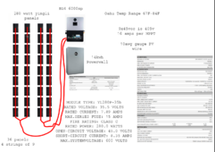


1710806393308.png
 
I’m also working on a similar project. Definitely not quite as many panels though.

I just ordered the EG4 6000XP as well w/new panels.

I’m setting up to run ZNShine 370w panels
41.0 VOC, 34.2Vvmp in a string of 10. I have 6 more panels that I’ll set up and point due east to catch early morning sun and get the bank charging earlier, I’ll then use all my 250w panels laying around for my back up 24v system.

I’m assuming you’re planning on running the PE bar to ground from the unit yeah? I’ve never grounded my panels directly before, just + and - into the controller with a ground running from the breaker box or inverter to ground. Based upon what I’ve read, the charge controllers ideal range is around 350-385vdc. You may want to consider running a 10th panel, your VOC will be under the max and your operating will be closer to the ideal range (at least from the research I’ve done so far lol) either way that’ll be a solid setup!! Definitely following your build!
 
I have 36 Yingli panels (280 watt)

I have and eg4 6000xp and the eg4 battery on the way to me.

Planning on running 4 strings of 9 panels to stay under the 480v limit of the 6000xp.

Should I add a combiner box or a fuse to each string or will the 16 amps per MPPT be fine.

Also-- I have seen a few videos where people say that I shouldn't ground the panels if they are going into an 6000xp. Should I be running wire in between all the panels and down to the ground or is there grounding built into the 6000xp unit.


I understand that the 6000 xp comes with a PV switch in the box.


More on the panels

MODULE TYPE: YL280P-35b
RATED VOLTAGE: 35.5 VOLTS
RATED CURRENT: 7.89 AMPS
MAX.SERiES FUSE: 15 AMPS
FIRE RATING: CLASS C
RATED POWER: 280.0 WATTS
OPEN-CIRCUIT VOLTAGE: 45.0 VOLTS
SHORT-CIRCUIT CURRENT: 8.35 AMPS
MAX.SYSTEMVOLTAGE: 600 VOLTS


View attachment 202919

Array sizing looks good with 25A being the short circuit max you would be fine. It would be worth noting that each MPPT will only use 4,000W out of the max 5.040W on the array. Also, I would recommend ground the PV to a an earth ground but not at the inverters' PE Bus.
 
Array sizing looks good with 25A being the short circuit max you would be fine. It would be worth noting that each MPPT will only use 4,000W out of the max 5.040W on the array. Also, I would recommend ground the PV to a an earth ground but not at the inverters' PE Bus.

Why not ground the array frames to the inverter PE bus? Where should I ground it instead? My ground (#6 Cu) goes back to the house main, where it is bonded to N. That's the only place where I have an N-G bond.
 
Why not ground the array frames to the inverter PE bus? Where should I ground it instead? My ground (#6 Cu) goes back to the house main, where it is bonded to N. That's the only place where I have an N-G bond.

When grounding the PV at the inverter bus, we have seen this cause EMI at the inverter. I would recommend grounding the PV at the home earth ground or having a separate ground rod put in.
 
When grounding the PV at the inverter bus, we have seen this cause EMI at the inverter. I would recommend grounding the PV at the home earth ground or having a separate ground rod put in.

Weird! Do you know the nature of the EMI? Any idea if a good-sized inductor between the PV frame ground wire and inverter PE bus (at the PE bus) would choke the EMI? I'm thinking some #10AWG copper wrapped around a dowel, or some kludge like that. Has it been tried?

On the other hand...

Any idea how far away from the inverter I'd need to hook up to the mains ground, in order to eliminate the EMI? My mains is probably 25' from the inverter, but I've got a xfer switch (L1 and L2 only) about 6' away, nearer the mains, over #8 Cu. I could probably run an insulated ground through the existing conduit between the inverter and xfer switch. That would be easiest, but obviously it would still share a ground most of the run to the mains. Getting all the way (separately) to the mains ground is a non-starter.

Punching a hole for a ground rod through my 4" concrete garage floor doesn't sound like much fun, either.

But, if I *were* to drive a new ground rod in, which ground would you recommend I hook the EMT from the inverter to PV panel frames to? Depending on which one chosen, I'll either have different grounds between the PV panel frames and the conduit (on the roof), or between the conduit (in my garage) and the inverter PE bus. I'm leaning more towards hooking the conduit to the inverter PE bus, as that will be more generally accessible, and likely to be touched at the same time. After completing the install, the likelihood that I'll be on the roof and touching the PV frames and conduit at the same time is low.

Damn. I guess I should have remembered that ground isn't ground, when mixing AC and DC. I'm a digital guy, and the power guys fought this kind of stuff with every new design, in our digital com systems, when I was in R&D, 40 years ago.

TIA
 
Weird! Do you know the nature of the EMI? Any idea if a good-sized inductor between the PV frame ground wire and inverter PE bus (at the PE bus) would choke the EMI? I'm thinking some #10AWG copper wrapped around a dowel, or some kludge like that. Has it been tried?

The EMI can be generated when AC and DC voltages are grounded together because of the potential for ground loops and differences in ground potentials. When AC and DC systems share a common ground, it can create circulating currents and induce electromagnetic fields, leading to interference. However, I have not seen this tried and may potentially work.


Any idea how far away from the inverter I'd need to hook up to the mains ground, in order to eliminate the EMI? My mains is probably 25' from the inverter, but I've got a xfer switch (L1 and L2 only) about 6' away, nearer the mains, over #8 Cu. I could probably run an insulated ground through the existing conduit between the inverter and xfer switch. That would be easiest, but obviously it would still share a ground most of the run to the mains. Getting all the way (separately) to the mains ground is a non-starter.

I would recommend having the AC input and output grounded from the panels to the inverter. However, keeping the PV ground isolated from mixing the DC and AC on the PEBus of the inverter. As for grounding the PV panels, I usually see this at the main earth ground for the home or a separate ground rod typically 30' away from the main ground.
 
I’m also working on a similar project. Definitely not quite as many panels though.

I just ordered the EG4 6000XP as well w/new panels.

I’m setting up to run ZNShine 370w panels
41.0 VOC, 34.2Vvmp in a string of 10. I have 6 more panels that I’ll set up and point due east to catch early morning sun and get the bank charging earlier, I’ll then use all my 250w panels laying around for my back up 24v system.

I’m assuming you’re planning on running the PE bar to ground from the unit yeah? I’ve never grounded my panels directly before, just + and - into the controller with a ground running from the breaker box or inverter to ground. Based upon what I’ve read, the charge controllers ideal range is around 350-385vdc. You may want to consider running a 10th panel, your VOC will be under the max and your operating will be closer to the ideal range (at least from the research I’ve done so far lol) either way that’ll be a solid setup!! Definitely following your build

My roof has just enough room for strings of 10 but I thought maybe that would be too close to the maximum voltage (VOC 45v x 10 panels) gets me to 450 of a 480 volt limit. Would that be a problem or should I get as close as possible to the limit with out going over.

I'm buying these panels used for about $35 a panel and have lots of roof space so I'd even consider going to 40 panels.
I realize you're in Hawaii so not much of an issue when it comes to temperature, but still, I know Hawaii has seen a few cold snaps where it has gotten down in the 50's. You don't want to fry your charge controller by being too close to the 480 volt max when the temperature drops. It only takes once...
 
My 2 cents ...

1.) PV Module frames should be grounded either to your main grounding rod or to a separate rod if they are ground mounted any distance ... you don't mention how or where they are mounted
2.) If to a new ground rod, a bonding conductor should be installed between the rods
3.) Do not ground either of the PV circuit wires, I think this is where a lot of confusion comes in as many older systems required the -ve wire to be grounded and this is most likely what was being referred to in the videos mentioned
 
However, keeping the PV ground isolated from mixing the DC and AC on the PEBus of the inverter. As for grounding the PV panels, I usually see this at the main earth ground for the home or a separate ground rod typically 30' away from the main ground.
your recommendations are going to get someone hurt or killed.
The sole purpose of the grounding system is to make everything safe for people to touch.
A separate ground rod (earth connection) is not going to protect anyone.
You have to connect to the grounding system to be grounded. (Not the earth)
One grounding system for everything is a requirement, not a suggestion.
 
The EMI can be generated when AC and DC voltages are grounded together because of the potential for ground loops and differences in ground potentials. When AC and DC systems share a common ground, it can create circulating currents and induce electromagnetic fields, leading to interference. However, I have not seen this tried and may potentially work.
like 97% of electronics that plug into wall have their DC negative tied to the ground plug..
99.9% of computer power supplies, servers, basically all of the ones that actually have a grounding plug and not just 2 prong
anyway there usually isn't anything else to connect to since most of switching power supplies are housed in plastic.

Is this a confusion between grounding & earth ground, or ground vs neutral or something?
 
My 2 cents ...

1.) PV Module frames should be grounded either to your main grounding rod or to a separate rod if they are ground mounted any distance ... you don't mention how or where they are mounted
2.) If to a new ground rod, a bonding conductor should be installed between the rods
3.) Do not ground either of the PV circuit wires, I think this is where a lot of confusion comes in as many older systems required the -ve wire to be grounded and this is most likely what was being referred to in the videos mentioned
Roof Mounted.
 
your recommendations are going to get someone hurt or killed.
The sole purpose of the grounding system is to make everything safe for people to touch.
A separate ground rod (earth connection) is not going to protect anyone.
You have to connect to the grounding system to be grounded. (Not the earth)
One grounding system for everything is a requirement, not a suggestion.
Still scratching head on the not grounding AC - DC at the inverter....
 
Still scratching head on the not grounding AC - DC at the inverter....
I think jared is trying to create a floating DC system which could sometimes be "good" but the fact AC is all out these inverters it probably won't be safe.
I'm curious what their tech people have seen there that they are worried about some EMI thing.
Next we'll hear if you do it an EMI field is generated and turns on your garbage disposal when you have your hand in it!
I was thinking if you had enough power may be time travel?
 
Back
Top