diy solar

diy solar

Building the sickest ® VAWT ever. Brilliant minds unite please!!

hmm or is it more like how it is done in North America. In where the mains grid is 240V but then gets split into 2 x 120V. So in that context I should be aiming for 360V battery pack. It does makes sense though as my 3 phase 15Kw heater has a 400V rated power plug. As does my 11Kw EV charger.
 
A permanent magnet inside the spool makes a steady magnetic field, which doesn't help.

A piece of steel would do it, but would have eddy current losses.

A stack of lacquer-insulated steel sheets, like the one on right side of picture below, would be good.

View attachment 77116


In a motor, the air gap between rotor core and stator core is about 1 mm, maybe less.
With magnets moving past either end of a spool of wire as shown below, the magnetic field passes through about 100 mm of air (and/or copper) to reach through the coil.

View attachment 77117
Do you recommend it to be very thin layers of steel with some kind of surface layer on it or can I simply use a giant lump of steel that does not have any surface treatment?

The amount of steel scrap I have laying around here is considerable. I have always wanted to try and smelt it. Maybe even get into the jewelry craft ;)
 
Do you recommend it to be very thin layers of steel with some kind of surface layer on it or can I simply use a giant lump of steel that does not have any surface treatment?

Insulated, so electric current can't circulate from one lamination to the next.
What I see in transformers and motors looks like sheets about 1/16th or 1/32nd inch thick. Cut to shape, coated in lacquer, stacked to form the core, arc welded together in a couple spots. Some are held together with inserts, acting like rivets.

 
ugg, I meant 3 x 240 V = 720V battery pack. if that can be charged by this alternator then it should be fair to say that this is officially the most sick(r) alternator to have ever been constructed.

With hundreds of volts DC, not just 48VDC like many forklifts and off-grid inverters, much greater shock and arc hazard.

My PV strings are 480Voc on a typical day. With switches, touch-safe fuse holders, and MC connectors, I'm able to isolate them without having to use a screwdriver or wrench on any hot terminals.

There is probably not a good reason to have such high voltage battery pack for consumer use, outside of EVs. Inverters for 48VDC can deliver 5kW to 25kW AC at 220 or 240VAC, and AC is easier to control and break.
 
The amount of steel scrap I have laying around here is considerable. I have always wanted to try and smelt it. Maybe even get into the jewelry craft ;)

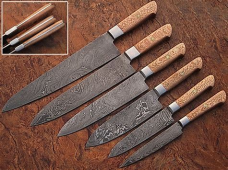
Could make Damascus blades. Much of the value is in the artistry and visual appeal.

For magnetic circuits, uniform thickness sheets from a steel mill would be better. You could also get superior alloys. Silicon steel is used in some transformers, especially toroids, which can be closer to 98% efficient compared to 80% or so for small "E" core ones.
 
There is probably not a good reason to have such high voltage battery pack for consumer use, outside of EVs. Inverters for 48VDC can deliver 5kW to 25kW AC at 220 or 240VAC, and AC is easier to control and break.
I am not sure but I still think I want to be able to run 3 phase loads. Some of them well over the 240Vac threshold if I understood correctly,

Anyway I liked your suggestion about Damascus blades so I poured me a set. Look at these first try results
1640538882075.png

Obviously a random image froma random website ;) but would it not be cool if one can forge something like this?
 
I am not sure but I still think I want to be able to run 3 phase loads. Some of them well over the 240AV threshold if I understood correctly,

You can get 3-phase inverters.
Easiest way to run 3-phase motor is with VFD. That is normally fed single phase or 3 phase AC. Should be possible to feed DC. Maybe PV direct, if voltage open circuit is within range, and speed adjusted according to available power (that is to keep capacitor voltage around Vmp).
 
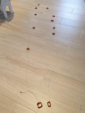
crap alternator (that cheap chinese one) destruction phase has commenced. I got one coil phase untangled after what seemed an eternity,
1640610875748.png
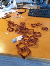
But fear not gang. The other 2 are really cooperative ;)
1640610998579.png

On the untangled single phase coils string I notice how uneven the coils and the length of coil connecting (single strand)wire between the coils are. It must be in an effort of reducing the cogging otherwise this looks just silly to an untrained eye like mine ;)
 
Last edited:
ahh to refresh one's memory. the crap coil wire is 0.4mm. But I might stop calling it crap as, if I understood correctly, wires can be thin as long as there is not too much amps running through. So a 360v battery could be charged with an 0.4mm wired alternator if I am getting the hang of this (i.e. finally udnerstand a bit less about the subject matter.).
Only it can't ever supply the more robust loads but that could be solved in other ways.
 
yeah.. no!... screw this untangling of this crap wire ;)

SO gang. I can get up to 20 kilo's worth of almost any sized enameled copper wire on a single spool in the meantime.

Do I get 0.4mm or larger? 1.0,mm is too unwieldy.

Let's settle on a 96v280A battery pack then as a goal. Conversions to more potent loads can be done later.

0.4mm or bigger?
 
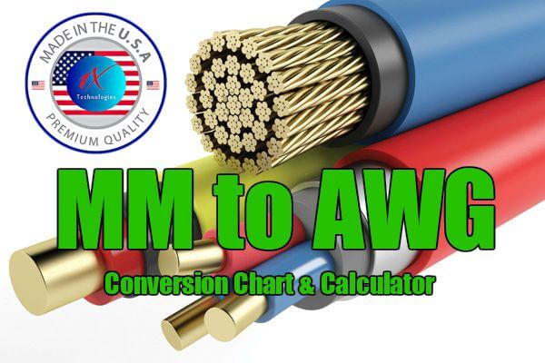
Here's one chart with ampacity and metric sizes.
Temperature not given. 20A for 12 awg sounds like house wiring.
In a coil, multiple layers would interfere with heat flow. But lacquer not thick plastic insulation is better.
This is a starting place, anyway, down to 0.05 mm

 
I just wanted to let you guys know that I have not abandoned this project.

On the contrary!!

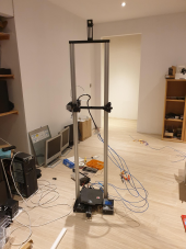
I have gotten a 3d printer in the meantime and am now in the process of modifying it to be able to print huge(R).

Reason being is that the several iterations of the magnet disk all had issues. The most recent was 3d printed in 8 parts as the default print bed size of my printer is only x220 x y220mm. Having components in many parts is wobbly and crap.

Also for the turbine blades I need a z axis that is syco(TM) as to be able to print them in only 2 parts rather than who knows how much.

1644823318888.png

Once the z axis is sorted I'll print the x and y axis profiles so that I can modify the printer some more and print the generator parts in single pieces.

I've already got a tempered glass panel of 4mm thickness that will serve as a larger print bed.
 
Reminds me of an X-Y plotter, a 3' x 3' Etch-a-Sketch, I built as a college project.
Stepper motors and zero-backlash lead screws moved two carriages on linear ball bearings.
One more piece at the intersection carried a relay, which held the pen.
Motor drive was switch-mode current sources (or at least was supposed to function that way.)
Programmed in Forth, and I hierarchically defined line segments, text, symbols. It drew a schematic of itself.


It was very wobbly, made wiggly lines.

Once you've got a wider base for your printer, consider guy wires to secure the uprights. (like your VAWT or HAWT may have.)
 
@brandnewb - Please remind me why you insist on 60 RPM operation. I'm not sure if I ever caught that in reading through the thread. As others have mentioned, power output will increase substantially with higher RPM.
 
the wind speed distribution where they are located, i forgot. but hazy memory suggests that there are many hours of "weak" winds

thus to seek optimized production at low rpm with larger diameter and/or larger surface area

sorry if i mistake :)
 
@brandnewb - Please remind me why you insist on 60 RPM operation. I'm not sure if I ever caught that in reading through the thread. As others have mentioned, power output will increase substantially with higher RPM.
Welcome Justgary to the party.

Needing a low rpm for the blades to spin at has to do with safety. I can't have one fling off at such speeds that it will kill the local wildlife, i.e my wife ;)

To compensate for the reduced power output at 60 - 120 rpm as opposed to much higher rpm, I will use 96 magnets with 128 coils (96 on each side of the magnet disk) of 100 turns each per phase.
 
for example. a cheap horizontal windturbine I purchased had but 12 magnets and 36 coils (12 coils per phase). Since I am going 8 times denser than that I think I can spin 8 times slower to get the same output if we ignore all other factors like magnet strength and coil length etc
 
Reminds me of an X-Y plotter, a 3' x 3' Etch-a-Sketch, I built as a college project.
Stepper motors and zero-backlash lead screws moved two carriages on linear ball bearings.
One more piece at the intersection carried a relay, which held the pen.
Motor drive was switch-mode current sources (or at least was supposed to function that way.)
Programmed in Forth, and I hierarchically defined line segments, text, symbols. It drew a schematic of itself.


It was very wobbly, made wiggly lines.

Once you've got a wider base for your printer, consider guy wires to secure the uprights. (like your VAWT or HAWT may have.)
I imagine I need to folow your suggestion to secure the printer at that height. The final goal is to make it 1200x1200x2300mm with a core xy (the bed does not move).

But what I meant to say was that having a magnet disk consisting of 8 individual parts glued together is wobbly and no good. That is why I am modifying the printer now so that I can print huge disks as a single component.
 
Back
Top