diy solar

diy solar

Building the sickest ® VAWT ever. Brilliant minds unite please!!

A rigid blade, fixed pitch, could have correct pitch at any given radius, matching air velocity. Faster wind, higher RPM should still match.
Variable pitch by rotating rigid blade would be sub-optimum at all but one angle of rotation.

One small wind turbine vendor described a blade that twisted and changed pitch by centrifugal force. "Works in theory ..."

But now, I'm starting to ponder as well about also adding wind concentrators (venturis) into an effective wind turbine...

Forget it. Turbulence is the enemy of airfoil lift.

As for inefficiencies of my DIY turbine. I will compensate for that by making it BIGGER(TM) :)

And pray for mild weather?
Better work on self-furling designs.
 
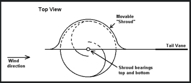
As far as VAWTs, I had been pondering about shrouded designs on those as well, like this example...


Or also the 'shaded' style:


or

1645038023281.png
 
A rigid blade, fixed pitch, could have correct pitch at any given radius, matching air velocity. Faster wind, higher RPM should still match.
Variable pitch by rotating rigid blade would be sub-optimum at all but one angle of rotation.

One small wind turbine vendor described a blade that twisted and changed pitch by centrifugal force. "Works in theory ..."


Forget it. Turbulence is the enemy of airfoil lift.


And pray for mild weather?
Better work on self-furling designs.

Hehe, well humans have been making wind mills for hundreds if not thousands of years, and still nobody has really mastered it...

I'm reading books though, and willing to give it my best shot too though...

I can scroll through pics of these for hours and just chuckle at the creativity... Maybe there is no perfect 'right' way to do it, or real wrong way, the proof is in the watts you are getting (or the amount of wheat you can turn into flour), otherwise it's just for looks (gives all the tree-huggers driving by your place, the warm fuzzies)...

 
Last edited:
A rigid blade, fixed pitch, could have correct pitch at any given radius, matching air velocity. Faster wind, higher RPM should still match.
Variable pitch by rotating rigid blade would be sub-optimum at all but one angle of rotation.

And, what is good about a blade where only a 6 inch section (x3 if 3-bladed) of it is at the optimal AOA at any given point (when the rest of the blade is stalling)? Not much torque can be provided by such a small surface area. Like I said before, those twisted blade designs are also to try and make a static pitch blade work a little bit better than it would normally.

Large industrial wind mills all have variable pitch turbine blades. All the more expensive airplanes also use variable pitch props too... Now even a variable pitch turbine should have some twist in it to compensate for the radius distance vs blade speed differential (center-to-edge)... but windspeed is a whole other beast, in relation to blade RPM, so AOA control helps optimize torque, but we want to have optimal AOA all the way along the length of the blade to get max torque (taking advantage of the surface area of the full blade).
 
Last edited:
Forget it. Turbulence is the enemy of airfoil lift.

Not turbulence. Increasing windspeed and pressure is the goal, not creating turbulence. A turbocharger on a car, wouldn't work as good if you just had the exhaust pipe sitting in front of a fan blade. A concentrator (turbocharger turbine housing) helps direct all of the exhaust backpressure into the turbo inlet (reducing inlet diameter size, increase airspeed and pressure onto the turbine impeller blades), so none of the heat or expansion is wasted to go around the turbine blades.

Also the problem with a open-turbine without shroud-control, is the centrifugal energy causes the air to spread outward as it travels through it, and it goes out toward the tip of the blades, and then gets wasted and turns into turbulence at the blade edge. Remember when they started putting the flares on the tip of airline airplane wings to reduce turbulence which was reducing fuel economy... Nowadays, prettymuch every airline has upgraded their planes to put these flare foils on the wingtips to reduce this turbulence.

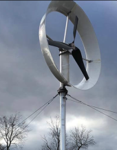
I think at least bare minimum, the style of shroud ring that some of the wind turbines have that help concentrate the air (and speed up the velocity) as it enters the foil, and keeps it in the funnel, so centrifugal force doesn't push it outward off the turbine tips creating turbulence would help get more efficiency.

I have also seen these rings have an airfoil shape to some of them as well, to help the pressure on the inside vs the outside of the ring, helping to increase the velocity on the inside of the ring going across the turbine blades.

Like these:

1645041074159.png
 
Last edited:
Thanks for pitching in @Samsonite801.

I am looking for words to say in the politest way possible that I will never again look at wind turbine sales information (or links) if they do not come with an upfront output graph (rpm vs output) and warranties to back that up with cherries on top.

Many scams out there unfortunately.

As for inefficiencies of my DIY turbine. I will compensate for that by making it BIGGER(TM) :)

Unfortunately bigger also means much beefier ground mount solution. I saw one startup company in an article that wanted to build a much larger wind collector/shroud for their turbine design to optimize it, but the ground mount required to support storm level winds made it financially impractical, and they didn't have the funding, so they built the tower at a lower height, but then it wasn't high enough to capture the 'good' winds, which they say is about 65ft above unobstructed ground level, so since theirs was like half of the optimal height, the POC failed to produce the desired results, and they couldn't get more funding to keep going on the project and folded-in, like so many other wind startups...
 
One thing I still have not figured out though is how to scale the blades. I mean my turbine will have a 2m diameter and a 3m height. How large doe the airfoils need to be at that scale?

I cant find anything anywhere.

Best I was able to do is reverse engineer from measurements I found in scientific papers that I did not even understand.
currently I have 117mm chord length (that is the length from the middle of one end to the middle of the other end)
 
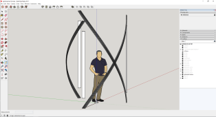
this is what I have at the moment
1645049228734.png
2x3 meters. 3 x straight airfoils and 3 x helix
but how to scale those damned airfoils I really would like to know
 
Last edited:
@Samsonite801 Also keep in mind the higher the rpm the more noise your neighbors can fall asleep to ;)
Did you find anything in the books you have read regarding the scaling of airfoils in VAWT's?

Not relating to VAWT, I haven't even gotten much into all my books yet. I am still on the first one (I just started getting more interested in this lately again), I mostly get distracted with content from the Internet, and then download more books. I now have 25 large PDFs (some books, some white papers) to read, and 2 Kindle books to start on. I see lots of math in them, which isn't one of my strongest points (might have to take up a passion in math hehe).

Are you hell-bent on going with VAWT as of now I take it?

I still haven't decided, but if I do go VAWT, I will research only with shrouded/shaded designs, because I don't like the idea of the loss involved with the returning blade upwind... Or if you can get the cost of one down cheap enough, one could handle a bit of inefficiency and scale up with more smaller units...
 
As far as VAWTs, I had been pondering about shrouded designs on those as well, like this example...

I think a shroud can help a drag-type device, like an anemometer, similar to some of the pictures you showed.
For an airfoil that produces lift, the shroud attempting to duct air into it for higher wind velocity causes turbulence, which kills the lift.

Large industrial wind mills all have variable pitch turbine blades. All the more expensive airplanes also use variable pitch props too... Now even a variable pitch turbine should have some twist in it to compensate for the radius distance vs blade speed differential (center-to-edge)

A twist to the blade, yes, so angle of attack is appropriate for speed at that radius.
But I think variable pitch, rotating each rigid blade about an axis, provides optimal angle of all parts of the blade only at one pitch setting, any other pitch sub-optimum. That adjustment could be better than nothing for those applications, just not optimum. What I suggest instead is variable loading on the turbine shaft, e.g. by an MPPT controller. Not by the output vs. RPM characteristics of a generator feeding a fixed voltage battery.
 
this is what I have at the moment
View attachment 84057
2x3 meters. 3 x straight airfoils and 3 x helix
but how to scale those damned airfoils I really would like to know

The drawing is excellent, but I'm worried about the user standing in the middle. If there's no brake, they won't be able to leave in one piece. I realize the shaft and other components aren't shown for clarity, but if you don't have handholds as well, the user won't be able to enjoy the spinning as much since they'll be focused on maintaining balance.

;)
 
update ;(

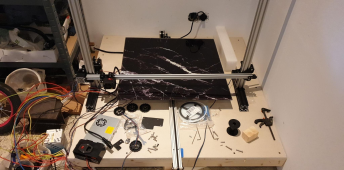
blew up my crap 3d printer controller board. with actual smoke.

it will take me some time to get past this hurdle

I am looking into going subtractive first and see if I can modify it to also do additive.

1647093605587.png
 
the print bed is 600x600mm and just too heavy for the poor stepper motor to fling around.

I am aiming at plain old cartesian rather than moving bed. what a crap idea that moving bed was to begin with ;)
 
keep in mind though that this is just a stepping stone. end goal still is 1200x1200x2300
Why so big? I see no reason that you couldn't print the wings in sections and glue them together. RC model folks do this all the time.
 
Back
Top