diy solar

diy solar

Building the sickest ® VAWT ever. Brilliant minds unite please!!

Because your design has rotating magnets in the middle and coils on both sides, I don't think Halbach benefits your design.
Instead, I think pole pieces through one coil and wrapping back through adjacent coil, to short out air gap on backside of coils, is what's needed.
Ok, so opposing fields, even though in a different arrangement, axial in this case, than a radial setup is still considered hallbach? if that is the case then sure. I stand corrected.

Anyway, can you please point me to some kind of graphical representation of what you are guiding me towards?
 
Here's the axial equivalent.
Note two or four windings facing rotor, with core wrapped out one core and in the next. All connected to a metal pole piece connecting them.

 
One thing to keep in mind is that if you only have coils on one side of the magnet disc then you are going to end up exerting a significant force pushing the disc away from the coils.

This will happen whether you choose hallbach, or backiron, or any other method to strengthen the field asymmetrically.

I suggest you consider having coils on both sides of the magnet disc, mainly because I don't believe your current design is mechanically stable enough to resist the forces that your design will push on it.

This will provide an equal force on both sides, so the only force you'll have to deal with is radial.

I doubt your current design will handle the desired power output/input radially either, but one problem at a time is better than trying to deal with multiple problems at once, and your current design will be fine up to a certain power level so it will be good for testing and ramping up the total energy transfer in the system.

You can, of course, continue to design and experiment with an asymmetrical axial load, but you'll find that the disc flexes away from the coils during operation, reducing power output significantly, which may leave you scratching your head unless you can measure the distance between the disc and coils while it's rotating.
 
you are totally correct. I wanted to do some testing by now ages ago it seems and the disk was going all over the place.

Currently the outer part of the disk (what holds the magnets) are 8 separate pieces as my printer was too small.
So that is what prompted the whole 3d printer extension side project that unfortunately blew up quite literally ;)

So once the printer is running again in it's larger format I will print the disk again from a single piece including all the way to the center where it will eventually connect to a bearing that is attached to a rather large steel column.
 
I think the forces will generally be pulling pole pieces (if used in coils) toward magnet disc, not pushing away. Permanent magnets will pull or push each other depending on orientation.
With coils & pole pieces on both sides of disc and no rotation, the attractive forces will be balanced and magnets/disc won't try to move either way if perfectly centered. If off center, it will try to move further off center. May twist to touch one side with one end, one side with other end.

With rotation, coils will only influence forces if circuit is completed so current can flow. They will always resist motion, whether magnet is beign pushed toward pole piece or being pulled away, unless current is forced through the coil externally (including by another coil.) Without pole pieces, coils with completed circuit will resist all motion that alters magnetic field strength through center of coil.

Once you connect a circuit like a diode, the circuit will be open when diode block current flow (including because voltage on one side is a sine wave curve before it rises above voltage on capacitor at other side of diode.) Mechanical force from the coil will only be experienced when current is able to flow.
 
I have taken a look at your coil field wiki suggestion.

I think I am already planning the same but am not sure. Please help me determine ok?

1650979868328.png
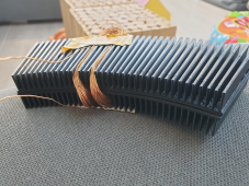
So what one sees here is 2 x 1/8th of the coil holder prints back to back.
Currently they are not yet printed using a ferromagnetic filament.
Also this demo is just to show you guys what direction I was planning and not the actual winding method I will use going forward. It's just a coil I had laying around.

So basically there is a single coil of a single phase with 100 winds of 0.4mm wire. Now please picture the whole disk filled with all 3 phases.
It will be jam packed with wires ;( ;)

I intend to engulf the whole disk with iron powder that is not electronically conductive to enhance magnetic flux.

I had planed to also fill the magnet disk with iron powder just before the top layer is printed. That will make for some awesome amount of flux enhancing if I have my theory correct.


Looking forward to suggestions or a good old pad on the back motivating me to go on ;)
 
it should go without saying that if this indeed is a good way forward then I'll be printing the coil holders (as as some of you may have missed I will be having 2 coil disks. please take a look at my avatar image) as a single piece. Not back to back no gluing, pinning no nothing that will negatively influence the stability of the structure.
 
the only thing I am worried about when using this winding concept, basically that one winding direction is further away from the flux source than the other, is the iron powder can not saturate all the way through resulting in an unbalanced coil
 
I have taken a look at your coil field wiki suggestion.

I think I am already planning the same but am not sure. Please help me determine ok?

I don't follow this coil orientation. Expected multiple solenoids facing one direction, but I see solenoids tilted steeply so (without core), field would extend from one to the next almost like a single larger solenoid.

Maybe that does work, with ferrite core ducting flux from each coil through its "fins".
Is that every 3rd slot because all part of one phase?

You have two back to back "heatsink" shapes, which has "fins" offering the magnetic field (or to receive field) from both faces. But only one face will have magnet rotor next to it, and you will have coils on both sides of rotor, correct? (Or, is that one set of coils and magnet rotors on both sides?)

The structure I usually see looks like a single "heatsink" (not two back to back) with windings on it in a planar fashion, around "fins" not around the "spine". And the coils may overlap each other, each going around multiple "fins", which makes it more complicated to understand. What I hand-wound as a kid was like in the Wikipedia picture - two "fins" and two coils, not overlapping.
 
the only thing I am worried about when using this winding concept, basically that one winding direction is further away from the flux source than the other, is the iron powder can not saturate all the way through resulting in an unbalanced coil

Saturation, as I am measuring it, occurs if I put a certain amount of current through a coil (and no cancelling current flows through another coil). Above that current, no further magnetization occurs and inductance decreases to air-core. No harm, no foul.
Doing similar by applying voltage, bad things can occur. With DC or too low a frequency, after a brief time current rises until saturation, then inductance drops by a factor of thousands and current shoots up to whatever DC resistance allows.

For a generator, I think saturation would mean you don't get any more current from it, and magnet moves freely without much resistance.
There is something about how core couples flux to [other] coil, and a loss of coupling if insufficient core, so their fields don't cancel each other. Probably leakage flux occurs and can be measured.
Core shape probably affects field strength in one part vs. another, like current distributing according to resistance in conductors, but with different current density due to cross section and shape. The skinny parts might start leaking first.

Imbalance from one portion of the rotor vs. another due to asymmetry could induce mechanical vibrations.
Non-uniform flux density through the coils probably isn't any big issue, just less efficient utilization of materials.
Force one wires causing them to bend/vibrate I think will become an issue at higher power. Probably need to be potted or lacquered into place so mechanical force is transmitted through the potting rather than by torsion on dangling loop ends.
 
ferrite core
ferritte seems best applicable in high frequency applications. Not for something around the 100 to 200 Hz I am going for.
Is that every 3rd slot because all part of one phase?
Indeed. There will be 3 phases eventually. No I only show a single coil.
But fear not. I can wind in many other ways. However the 3 phase concept is static and also the heat sink style holder is static.
You have two back to back "heatsink" shapes, which has "fins" offering the magnetic field (or to receive field)
It will be receiving magnetic flux.
The magnet disk will have one of the coil disks I just showed on each side. Please take my avatar image as a heads up. Although it is outdated it is still in general terms what I am gravitating towards.

Expected multiple solenoids facing one direction, but I see solenoids tilted steeply so (without core)
Yes, this is what I meant with what I am worried about. But this only applies if the ferromagnetic filament (in the final version) and iron powder (in the final version) is not able to get saturated enough to fully engulf the coil with the magnetic flux. I am actually thinking it probably will not.

The structure I usually see looks like a single "heatsink" (not two back to back)
Yes I know. But my god it is freakishly difficult to wind coils in only 2 dimensions like that ;( So hence I thought going in a 3d dimension.
 
I don't follow this coil orientation. Expected multiple solenoids facing one direction, but I see solenoids tilted steeply so (without core), field would extend from one to the next almost like a single larger solenoid.

Maybe that does work, with ferrite core ducting flux from each coil through its "fins".
Is that every 3rd slot because all part of one phase?

You have two back to back "heatsink" shapes, which has "fins" offering the magnetic field (or to receive field) from both faces. But only one face will have magnet rotor next to it, and you will have coils on both sides of rotor, correct? (Or, is that one set of coils and magnet rotors on both sides?)

The structure I usually see looks like a single "heatsink" (not two back to back) with windings on it in a planar fashion, around "fins" not around the "spine". And the coils may overlap each other, each going around multiple "fins", which makes it more complicated to understand. What I hand-wound as a kid was like in the Wikipedia picture - two "fins" and two coils, not overlapping.
my daughter is bugging me. i'll get back to this
 
ferritte seems best applicable in high frequency applications. Not for something around the 100 to 200 Hz I am going for.
hmm maybe you are correct after all going for high frequency.

After all we are dealing here with 96 coils per phase that get excited 96 times per second in a single direction or double when we take into account the negative flux.

What kind of Hz are we looking at here? But then still I think this is not a high frequency application
 
I am still hoping that this 96 magnet arrangement will blow anyone's expectations. I certainly it will do mine.

But to give one a heads up I think I am looking at around 90 volts at 60 rpm per disk. so lets call it 360 volts max ( at 120 rpm) when this project is finally going to see progress and has 2 coil disks.

I still think that 360 volts is worth the SYCO definition though
 
120 RPM x 48 field reversals / 60 seconds per minute = 96 Hz.
A low-frequency direct drive turbine design. No gear train so less drag. Very high magnetic forces required to apply enough torque to be interesting.
Have you calculated the torque for say 30 mph (or your metric equivalent) wind speed?
How does strength of rotating disc, stationary armature, and method of securing them compare?

Normally such things would be constructed of steel laminations, which are far stronger than plastic. Fiber reinforced plastic isn't as bad, and shapes can be designed to spread out and have sufficient material in width as material in circumferential direction reduces. But up to a point, speed trumps brute strength. That works against wind turbines, and for turbochargers.
Typical motors are 60 Hz 3600 RPM. Stepper motors and your design use more poles, lower RPM and higher forces. EV's and airborne systems use 400 Hz 3-phase motors, maybe 24,000 RPM. Light weight DC brush-type motors are also high RPM.

Besides bulk material strength, stress concentration is a big issue. It is proportional to radius of inside corners. So while a disk may appear strong enough, crack initiation at bottom of a "fin" or corners of magnet holders could lead to failure.
And then there is vibration and resonance. That can lead to localized forces far higher than average static load.
yes sir!! hence my effort to reduce the radius
 
But yes sir, of course you once again have valid points.. I now am in a split ;( do I use carbon fiber reinforced filament or iron filled filament? ;) I do not have a filament that has both properties ;(

nah don't worry. we are talking about 120 rpm at max here.
 
yes sir!! hence my effort to reduce the radius

But I meant maximizing the radius of any inside corners.


But yes sir, of course you once again have valid points.. I now am in a split ;( do I use carbon fiber reinforced filament or iron filled filament? ;) I do not have a filament that has both properties ;(

Composite 3D printed structure, alternating filaments?

nah don't worry. we are talking about 120 rpm at max here.

So no centrifugal force to worry about. But higher magnetic forces needed, to deliver same power.
 
Back
Top