diy solar

diy solar

Building the sickest ® VAWT ever. Brilliant minds unite please!!

what also does not look good on the last photo is the spacing of the magnets. I think I messed up as what I want to see is a uniform spacing on both disks and synchronous yet opposite in field (although we do not get to see the field by eye)

I will go back to sleep now and give this and the coil casting a once over in the morning... probably Monday I will report back
 
I do not think 52 vAC at 3.7 hZ is a realistic goal with 0.71mm wires.

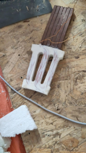
With a 100 winds coil twisted into 100 200 100 leg wires in 15mm thickness (so making the legs 12mm wide did help with pressing the coil)

1711202442489.png

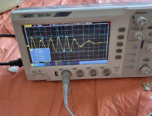
generating lets say 1.6vAC at around 3.7Hz. Now I do see quite a bit of space left in the legs so I can get more wires in.

1711202531044.png

In it's current configuration extrapolating to 31 coil legs that would make for 6000 leg wires in total. only generating 24 vAC at 3.7 Hz

So it does not look good if I really need that goal of 52 vAC using this 0.71mm wire.

Would not aiming for 33 vAC be enough? as then after rectification we would end up with 52vDC if I understood it correctly that 3 phase AC to DC would increase the voltage by 40%
 
Can you get the speed up enough to do 50Hz or 60 Hz?
At low frequency and low speed, need higher force for same power.

(The casters are probably only meant for pushing speeds. Doesn't say "Not for highway use" because they never thought anyone would try it.)

But don't kill yourself with things flying apart by centrifugal force. Automotive flywheels come with a warning about high RPM, that even firewall won't stop the pieces. You do have many poles, so shouldn't need 3600 RPM, more like 36 or 72 RPM. A drill/driver might do it.
 
Hi to you all. I'm new to this forum, since just a couple of weeks ago. But I have lived completely off grid for the last 25 years here in the UK. I started to read this thread as I have an interest in WT but I confess that i have not read all 83 pages so forgive me if i say something you already know.

I have built and flown successfully 3 home brew wind turbines. All created using the Hugh Piggot receipe book. I see that at the begining of this post pages 1 and 2 there is ref to Hughs book and also the guys at Fieldline. Hugh is the man. His books tell you all you need to know. He is also approachable and willing to give time to help peoples projects. But unless his opinion has changed in the last couple of years he would advise no to VA WT.

I first built a 2.4 mtr 3 blade turbine, with carved wooden blades, which I later upgraded to a 3mtr model. I then went big time and built a 4.5 mtr unit. Wound all the coils (with a home made former) cast the mag rotors etc . All 3 units worked well, not the most efficient but reliable and bomb proof. The 4.5mtr dia unit would regularly turn out 3 Kw annd the max production in a day was >40Kw.

I have never considered building a V axis unit. Many appear to have tried but I have never seen any real word performance/output figures from anyone DIY or manufactured. In the absence of proof of concept I prefer to spend my time on achievable goals so I stuck to the horizontal axis concept.

I can't help but wonder what you objective actually is. The facts about building WT's are well known and documented and you could have built a turbine in 2 months DIY work and been producing power for the last 2 years.

If you wish to purchase a reliable WT on a domestic scale might I suggest you take a look at https://sd-windenergy.com/. I have also had one of their 3Kw turbines for the last 2 years and it is bomb proof. It is horizontal axis with down wind auto furling blades and is safe to run with no load connected. It can be purchased as either for battery charger or as an AC coupled unit.

One common factor of both VA and HA wind turbines is they need to operate ideally in clean air. Proximity to buildings, trees and uneven terrain all reduce efficiency in an incredible fashion. AND NEVER think about fitting a turbine to your dwelling. The noise and vibration is phenomenal and if your WT self destructs it may also damage your home.

I don't want to sound like I'm pissing on your parade but I think you may be on a long path to nowhere. But if any of my real world experience is of help I'd be pleased to share.
 
That sounds like quite high output for small wind. Do you have graphs on wind speed? And what height above ground?
40 kWh/day is like what 7kW PV system might deliver, so quite impressive and useful.
 
WT is on a 12 mtr hinged tower. I should point out that the over 40Kw day was a 50Mph day with 70MPH gusts. Wind today about 25MPH. Today solar PV has done around 6K and the wind had made 14Kw in 14 hrs. I'm not obsessed with the daily data as I have too many things to get on with. So no I don't have graphs. When I started my journey we had an ancient Lister 3cl 12KVa genny. and nowt else. What I do keep records of is my fuel costs year on year for 20 yrs. The satisfaction for me is getting that spend down. I'll never expect to be 100% RE but this year I changed to an LPG powered genset., Dearer to run than the Lister but no oil or smell and service costs are lower.

Adjusted for inflation since 2001 Diesel costs 1st year 3000 Litre @ 80p/L = £2400
Last year on Diesel 2023 400 Litre @80p = £ 320

Should point out that the house is medium size 2500 sq ft. 1000ft up a hill and exposed. Unlike some off grid set ups I like to live comfortable so we have all the usual kit, ie automatic washing machine, dish washer, 3 deep freezes, fridge, LED lights all round. Wet, pumped UFH. House is always warm. I have recently installed a 3Kw ASHP to supplement the UFH. This ASHP is a dump load so if genny runs or the WT has topped off the batteries the ASHP starts up to burn of the excess. So the ASHP is effectivley running for free. Love it.
 
welcome @offgridandy

I envy you your offgrid status. especially for so long. if only I could ever get there.

I have both recommended books. one kindle of that book mentioned in the beginning of this thread and the paperback of the one referenced here rather recently.

The issue with said books is that they are about HAWTs in areas where they can spin really fast without the fear of killing someone when something unexpected happens.

Then my municipality will not allow for HAWTs with a wing span diameter of more than 2m. So basically rendering them useless.
Going VAWT here is an attempt to circumvent the poorly defined rules as stipulated by the municipality as they do not mention VAWTs at all.
 
Can you get the speed up enough to do 50Hz or 60 Hz?
At low frequency and low speed, need higher force for same power.

(The casters are probably only meant for pushing speeds. Doesn't say "Not for highway use" because they never thought anyone would try it.)

But don't kill yourself with things flying apart by centrifugal force. Automotive flywheels come with a warning about high RPM, that even firewall won't stop the pieces. You do have many poles, so shouldn't need 3600 RPM, more like 36 or 72 RPM. A drill/driver might do it.
it is starting to look like having to let go of the direct drive concept (rotational speed of PMA = rotation speed of turbine)

increasing the leg width to 12mm made so that now i can't fit 3 phases any longer when each phase has 31 legs.

and that is not even taking into account that I should be aiming for 37.14 vAC before rectification rather than 33vAC i mentioned earlier..
I used 52 / 1.4 to get to 37.14. this is assuming reification to DC indeed increases the voltage by 40%

1711261437227.png

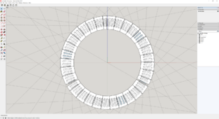
look how the end of phase c now overlaps the beginning of phase a when I rotate each phase by 121.25 degrees

arrrggggg

I am worried about the loss of torque when using gears and the added points of failure it introduces :(

one really great thing of letting go of a direct drive is that then we chould increase the speed by let us say 4 times reducing the total wires needed by roughly a similar amount so that now we can use fatter wires for the coil and then the field they produce will be much greater as there would be less resistance in the wires as now they are both fatter and less long.

ohh this makes me soo want to let go of this self imposed direct drive goal that I can almost taste victory :)
 
Last edited:
incredible.

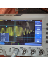
look what happens when i rotate around 4 times faster than 3.7Hz
1711264051187.png
the voltage jumps from 1.6vAc at around 3.7 Hz to 8.8vAC at around 4 times that speed.
not linear at all.

I guess this is physics telling in a very polite way to "stop trying to understand it, the way I work is above your paygrade. Just abandon this direct drive already and go gearing up!!"

hmm ok ok ok already mother nature. I will listen to you.
 
Last edited:
the voltage jumps from 1.6vAc at around 3.7 Hz to 8.8vAC at around 4 times that speed.
not linear at all.
This is why we keep mentioning higher frequency. A magnet sitting still near a coil produces no current in the coil. The magnet has to move to produce current, and it produces more current with more speed. It should be roughly linear except for capacitance in the circuit and as the coil nears saturation.

Try different speeds and make a chart for us.
 
"Saturation" is only a thing for cores. If no fill in his plastic, these are air core and don't saturate. ;)
Maybe something happens with the permanent magnet as moving coil with current in it interacts. Only at much higher speed.
 
Try different speeds and make a chart for us
Yes sir, will do!

Please allow again for some delay as I first need to source a 3 phase motor to drive the PMA. I already have the Variable Frequency Drive though.
As without said motor it will be really hard to get things consistent. And I guess now consistence is paramount if we start creating charts.

Now please do not feel uncomfortable that I only am getting this motor to please the gang. as of course I have had already in the back of my mind getting such motor.
Now though is the time to actually go and get it.

This is not to say that I would not get out of my way to make sure everyone here is able to keep taking things serious. Hence the recent book I bought and I also bought 16 over powered magnets that I will one day use to show that our PMA is still more syco ® than anything before it in history :) (this was through a thread on fieldlines on where I was told that what I am trying here can never work and should try something else)
I really need to be able to say something and people can believe it otherwise there is no point in going on like the way I am doing.
 
"Saturation" is only a thing for cores. If no fill in his plastic, these are air core and don't saturate. ;)
Maybe something happens with the permanent magnet as moving coil with current in it interacts. Only at much higher speed.
it could have been anything. for example the coils could have been touched by the magnets and because of the additional kinetic energy at the greater velocity perhaps the coils serendipitous got bumped/oriented in a more optimal way.

But I agree with Gary. Only well made charts can tell.
 
A magnet sitting still near a coil produces no current in the coil. The magnet has to move to produce current, and it produces more current with more speed
I do not think I agree 100% with you Gary. I do agree that you know 100% more than I ever will though :)

You see velocity does only so much. Yes I still say that even after having displayed the results above in where velocity seems to do more than linear.

I still am very much a firm believer of what Hedges once said. That it is about the frequency of field reversal. And that is because in many ways we can translate this to velocity. I know even you once said something here to a similar vein in where it all boils down to the same thing. And I really really think you were correct on that one!!

In the most basic of ways I think the most important aspect to get a good voltage is the speed at which the magnetic field changes. And the velocity of the magnets does play a role in that but even more effective way is to double the magnets at a given inner radius.

Now this is a careful balancing act though as I was unable to double the voltage producing capabilities of similar coils at double the inner radius (roughly double the velocity of the magnets)
So it got me thinking to get another 192 of these magnets and make the spacing similar to what they are at 300mm inner radius but then the velocity at which they traverse the coils is roughly double.

Why got I to that thinking?
This I think is because now (at 600mm inner radius at a 3.75 deg interval) the magnets are spaced too far apart and there is no more side ways interaction between them. And with coils shaped like the ones we entertain (meaning coil legs are running similar to the center of the magnets) that seems to be important to also keep most of the coil wires engaged.
 
and I forgot to mention that if the magnets get too close then there is no more field in between the rotor disks.

hence this careful balancing act I mentioned.

Now one can say what they want but this is not something I have read yet in any book or paper out there.

The only real way I can think of, other than the trail and error I do, is for something like FEMM software to give us a visual idea of what might happen. And then based on that go and confirm it.

But as we all know this is just too obscure and certainly not accessible for the grunt soldiers like me at the front lines.
I mean I can download it and run it but it is just not something I can use to get where I need to get because I lack the mental abilities
 
But I agree with Gary. Only well made charts can tell.
And I agree with Hedges in relation to the request for charts when newcomers come in and suggest that their small wind solutions do great.

Small wind never does... "great" I neglected to also mention that my municipality will not allow for a HAWT to be taller than 12m.

Can you imagine how many questions this creates? 12m from what? is one of course. But the fact of the matter still is that we here in the NL and especially on my land we have all kinds of elevations to consider. Most of them sub sea level.
 
and I forgot to mention that if the magnets get too close then there is no more field in between the rotor disks.

hence this careful balancing act I mentioned.

Now one can say what they want but this is not something I have read yet in any book or paper out there.

The only real way I can think of, other than the trail and error I do, is for something like FEMM software to give us a visual idea of what might happen. And then based on that go and confirm it.

Because I can see electromagnetic fields, I do the FEM analysis in my head.
Makes sense that magnets side by side would grab the field, not let it go through coil to magnet on opposite side.
I believe that can be helped by putting a core through the coil, so magnetic field sees the core much closer than the neighboring magnet.

Also, for the dual rotor (magnets) outside single stator (coils), I would put steel or other magnetic material disk on outside of magnets. Do you have that now, or is it non-ferrous?
 
I would put steel or other magnetic material disk on outside of magnets. Do you have that now, or is it non-ferrous?
According to my testing I found that one needs no more that 50% thickness of steel plating behind the bar magnets like we have here.
The logic here I will explain.

The bar magnets we have at play here are 60mm tall by 10mm wide by 5mm thick.
this means that 2.5mm of its thickness is of a certain polarity.

Now given that the grade of the magnets is N45. So even though really strong, not the absolute scariest there are (N52)
we can get away with about a steel backing of about the same thickness of a polarity (in this case 2.5mm).

Now in case I made a blunder in understanding I made sure that the steel backing was more than that and I went with 4mm steel plating.

I of course did my sanity test before starting to cut the steel to make sure that the readings were similar enough as if I were to put this type of magnet on a 13mm thick steel plate.

Yes similar enough so all system go.

So the steel backing you see is indeed a steel backing :)
 
Last edited:
ahh yes then one might wonder why the 10mm extension on both ends of the magnets? well that is because the field these magnets produce like to spread about 10mm beyond their ends. So I though why not help the field also there!!

no i meant the strongest parts of the field in that curve. one can measure micro teslas well beyond 10mm in that curve but at some point it is no longer worth considering
 
Last edited:
Because I can see electromagnetic fields, I do the FEM analysis in my head.
Makes sense that magnets side by side would grab the field, not let it go through coil to magnet on opposite side.
I believe that can be helped by putting a core through the coil, so magnetic field sees the core much closer than the neighboring magnet.

Also, for the dual rotor (magnets) outside single stator (coils), I would put steel or other magnetic material disk on outside of magnets. Do you have that now, or is it non-ferrous?
i have ran experiments suggesting that fields will happily circumvent a path with less permeability. So I am not sure that adding cores will help persuading the field from the permanent magnets through the coils is plausible.

Hence my hammering on adding iron powder through the wires of a coil leg.
But I still have no evidence that indeed helps voltage generation abilities. I will hold on to it though as it will increase heat dissipation abilities and lessen the cogging since now there is less of a difference between the coils and the cores in terms of permeability.
 
Back
Top