diy solar

diy solar

Bus bar basics

Bluedog225

Texas
Joined
Nov 18, 2019
Messages
2,959
Confession time. I haven’t paid attention to bus bars at all. It’s always been a topic for later.

I’ve got a question about setting up a basic little 12 volt system to power my shop lights. One panel, one little Victron charge controller, one SOK battery. But I want to learn how to properly do this for my 48 volt system later.

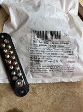
I’ve got this little bus bar that has a bunch of little 15 amp connectors. The entire busbar is rated at 180 amps at 12 V.

The 180 amps seems fine for all my needs.

In theory, the panel can produce more than 15 amps.

Can I stack two ring terminals on the “big” lug? One from the charge controller and one going to the battery positive? Or is stacking ring terminals a bad idea?

And on my “big” system later, is it best practice to tap into the bus bar with separate attachment points for each connection?

Thanks


F03D9977-421E-4FB9-B8AD-F790F32B678B.jpeg
BB7686D4-D319-46BF-AC5B-A9CE4B2E8892.jpeg
 
Separate connections is best. But you can stack two, safety. Always put the largest (amperage) one against the bus bar.
 
Like timselectric said, stacking is ok as long as it's done correctly. One thing to look for when stacking terminals is to ensure they are perfectly flat and 'mate' properly. Different size. shape and brand terminals can at times interfere with each other. Also, when stacking make sure the extra height of stacked terminals doesn't prevent the screw from threading into the busbar completely. Last thing you want is one or two threads holding your terminals to the bar.

Best practice is to avoid stacking and just get a bar with plenty of spots to attach and torquing to spec.
 
Got it on stacking. Thanks!

Big picture, for my future build, get a solid copper bus bar and use it as a universal connection point?

That is, all battery power and all charging amps go to the bar. And all the loads tie to the bar.

And the bar is sized to handle what? The max amps from the charge controller plus (???) max load? Or do I simply go with the higher of the charging current or the max load? Seems like the latter.

For example if I’m charging at 50 amps and drawing 100 amps, the bar would be sized to 100 amps, right?

I’m happy to read and study up if there is a resource.

Thanks
 
Bus bars should be sized for the maximum amps it could ever see at one time.
Right. I wanting to make sure my thinking is right. If the bar is receiving 50 amps and the load is drawing 50 amps, the bar seeing 50 amps. Right?

And if the bar is receiving 50 amps and the load us 100 amps, the bar is only seeing 100 amps, right?

Sorry to be dense.
 
How many batteries do you have? And what are the BMS ratings?
SCC ratings too.
 
I don’t have the 48 volt system yet. I wanted to understand the principles.
 
I don’t have the 48 volt system yet. I wanted to understand the principles.
I’m pretty sure it just depends on how many amps are drawn.

If your inverter/charger can only do say 200A, then that’s all that would travel through the bus bar.
 
Right. I wanting to make sure my thinking is right. If the bar is receiving 50 amps and the load is drawing 50 amps, the bar seeing 50 amps. Right?

And if the bar is receiving 50 amps and the load us 100 amps, the bar is only seeing 100 amps, right?

Sorry to be dense.
You aren’t “seeing/sending” more amps than the loads are drawing.
 
Last edited:
Inverter maximum amperage
Battery BMS maximum amperage
SCC maximum amperage

Pick the two highest and add them together.

If going with an AIO. Just choose the one highest.
 
Back
Top