diy solar

diy solar

BYD 24V LiFePo4 Battery Modules

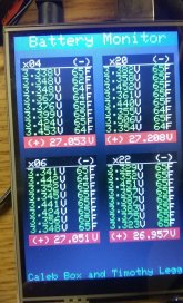
I bought 4 packs from battery hookup back in March. 3 of the 4 are good and giving me the expected 3K out of them when I did my initial capacity test as a stand alone 24V pack. I run them conservatively since they are used, but with a Chargery BMS they seem to stay working well together. I occasionally check the cells and they hover around 3.35V at full charge and I have the BMS disconnect at 2.75V. I haven’t had them that low except for the initial testing I did to see their capacity. Once below 2.65V the cells started to drift off quickly so that’s the window I use these things in. Unfortunatly I had one pack with a bad cell #2 which I decided to try to fix by wiring in a replacement Fortune Cell. We will see once I get it figured out how to safely wire it to the exiting bus bars and cut out the old cell connections. May be a waste of time, but I hate to throw out one pack due to a bad cell. Plus I’m using it in a 48v setup so I need two 24v packs to make it work and I enjoy the challenge.

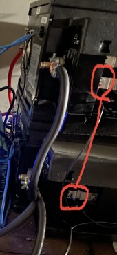
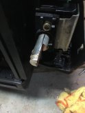
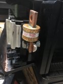
I decided to cut each main round battery terminal post down about 40% (just off of center) with a small 4” air Power diamond Cutting wheel giving me a flat side. Made easy work of it, just had to take it in 3 cuts so as not to over heat the plastics and melt the plastics around the terminals. I Then center punched the terminal and drilled and tapped to accept a 5/16 Bolt. Slow work and some cutting oil but it came out great and I think it’s a safer connection than forming round pipe to fit. I then bolted a T type fuse and also put a nut at the other end to ensure nothing would come loose. Seems like a solid connection to me. So far I have been happy with them, just had to spend time wiring up the Chargery BMS to each battery and realize their operating window is smaller than a fresh battery. Other than that, it was a great learning experience and have a new appreciation for how LifePO4 works and wiring them together. I follow Will and David and used their wizdom and others to help me, along with my New England ingenuity. Plus I’m not a complete idiot, just a 1/2 idiot :) Hope u enjoyed my brief build description.
 

Attachments

  • D166F830-4399-46C4-8FDC-FC2580A37DEE.jpeg
    D166F830-4399-46C4-8FDC-FC2580A37DEE.jpeg
    68.9 KB · Views: 60
  • 9E377EAF-123B-44F9-8017-957DC68B5C93.jpeg
    9E377EAF-123B-44F9-8017-957DC68B5C93.jpeg
    77.4 KB · Views: 62
Last edited:
So I also bought a pair of these.. One has a bit of an issue. Any suggestions on how to repair this problem on the negative terminal?

negative broke.jpg
 
I would not trust a muffler shop. You might try a small drill and a small, short self tapping screw.
 
Ok who has the laser welder in the garage? This will be a hard fix. Tap and pray best way?
 
I thought about getting Mig welding wire and using the battery itself ... they have the current ... why not
 
well if this is even remotely close my 2nd one with the good terminals is very nice.photo_2020-09-08_23-45-48.jpg
 
Anyone have any extra factory BYD BMS they'd part with? I killed one fidgeting with it. :( Trying to see if I can make them work.
 
I agree, I pulled the monitoring boards out, drilled out the rivets, re riveted in a proper bms lines all the same length, mounting the bms where byd board was, near the fan to keep cool.
Also got rid of the two front posts

I agree, I pulled the monitoring boards out, drilled out the rivets, re riveted in a proper bms lines all the same length, mounting the bms where byd board was, near the fan to keep cool.
Also got rid of the two front posts
what kind of T connector is that and where can we buy?
 
Little update, so far the BYD BMS temperatures and voltages have been sorted out, however it doesn't seem to balance under its own directives. I am continuing to crack at it. If anybody knows HCS08 or CANBUS I'd love to get some others involved. I have downloaded the ROM image off the BMS microcontroller, have multiple ways to get at the CANbus, and can get ahold of any information off the board you want with a scope or meter. I feel like I'm at 99% with it here.

If anybody wants to see the progress of the code its on a wiki my friend and I made to help keep it synced between us

I have put balancing on hold to start working on integration with an Epever(Epsolar) AN series controller. At worst case scenario, I can get a good balancer to attach and still rely on the BYD to send me cell info and temps.
 

Attachments

  • IMG_2342.JPG
    IMG_2342.JPG
    173.2 KB · Views: 16
So I also bought a pair of these.. One has a bit of an issue. Any suggestions on how to repair this problem on the negative terminal?

View attachment 22150
While gently hammering on some lugs today I realized one of my negative terminals has this exact issue! How did you end up fixing yours and how did it work?
 
So I also bought a pair of these.. One has a bit of an issue. Any suggestions on how to repair this problem on the negative terminal?

View attachment 22150
I also have a couple that got posts broken like this in shipping and have been sitting in my garage waiting for me to decide what to do with them… did you end up fixing yours? What method did you use?
 
I also have a couple that got posts broken like this in shipping and have been sitting in my garage waiting for me to decide what to do with them… did you end up fixing yours? What method did you use?
I did! Well I had a neighbor fix them for me. He ended up following the advice of this nice guy on Facebook and they have worked well for the last 6 months for me!
 

Attachments

  • CD3D81BB-E348-4127-8693-3B11B22FD30F.jpeg
    CD3D81BB-E348-4127-8693-3B11B22FD30F.jpeg
    221.9 KB · Views: 40
@Will Prowse - In addition to the discussion above here's a quick question. I bought two of these BYD batteries and now am going to add the Daly BMS you recommend. Instead of buying two BMS can I instead connect each corresponding cell in parallel to between the batteries (i.e. 8 sets of cells in parallel, then connect each battery in parallel. That will keep each pair balanced and provide 24V and 400 amp capacity. Then I use one BMS to keep the 8 cell pairs balanced.
The only issue then is that I have a maximum current requirement of 400 amps, for which I can't find an equivalent BMS.
You mentioned using an external relay in such situations, but I'm unclear as to how that would work. Can you elaborate?

Oh, and by the way, do you have a Patreon account? You are saving me so much time and money I feel I need to repay you.
Did you find a solution to your setup?
I have 14 BYD modules and would be more efficient if I can use one BMS for each 2.
Thanks!
 
Did you find a solution to your setup?
I have 14 BYD modules and would be more efficient if I can use one BMS for each 2.
Thanks!
I am actually retiring a set of 5. I used one dalygreen BMS and paralleled 5 packs with it. #6 x 1/2 self tapping screw can conveniently attach a ring lug to the fuse strips.

The more cells you parallel the better your balance will be, at least in my experience.
 
I am actually retiring a set of 5. I used one dalygreen BMS and paralleled 5 packs with it. #6 x 1/2 self tapping screw can conveniently attach a ring lug to the fuse strips.

The more cells you parallel the better your balance will be, at least in my experience.
Thanks for the tip.
I think I can see what you mean. If you can, would you mind sharing a schematics/photo of the wiring, just to be sure I am doing the right thing
 
Do this across all the cell groups. Connect all your - together, then all your 1+\-2 bars together, then all the 2+\3-... all the way up to all the positive terminals.

Be super careful... or your ring lug will turn into a spade.

Edit: i had occasional connection issues, lock washers are suggested.
 

Attachments

  • 0B8C96AC-B4B9-4383-8461-D49897E92877.jpeg
    0B8C96AC-B4B9-4383-8461-D49897E92877.jpeg
    498.1 KB · Views: 17
Back
Top