heirloom hamlet
life my way
In fact, would this package work well in my case and keep things simple for me? It is this the same basic thing, correct?Conclusion:
Molex Micro-Fit 3.0
430251000 10POS 3mm Molex Micro-Fit 3.0
or
1729521001 Micro-Fit TPA Receptacle Housing WITH Micro-Fit Terminal Position Assurance (TPA) Retainer
Molex
4303000001 12" PRE-CRIMPED Molex Jumper Wires
or Crimp your own wires
Micro-Fit 3.0 Crimp Terminal, Female
TE Connectivity AMP Connectors
1318772-2 12POS 2.2MM Tyco Electronics Header
1318745-2 32POS 2.2MM Tyco Electronics Header
Dupont Wires
Female to Female Jumper Cables
The Male to Male jumper cables, sort of work, but are very loose. If you are comfortable with them, you do not need the TE connectors.
The Molex connector on the BYD fan panel:
The connector has pretty much no standard on the backside. I have 3 different ways it is wired on my BYD batteries. Use the jumper cables to the outside panel.
The only thing that is standard, is the fan 24V position on the far left.nevermind this, just look at the pictures a few posts after this
24V R B B B B
24V R B B B B
or
24V B B B B R
24V B B B B R
()
It's just a color and a connector. Connect the jumpers so the Molex Connector on the outside is
_ 7 5 3 1
_ 8 6 4 2
Wires on the battery side on my BYD's are the same for all 8.
- - - 7 5 3 1 ---------
- - - 8 6 4 2 ---------

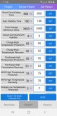
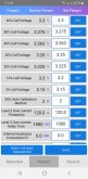
8S-20S Smart Li-ion Lipo Lifepo4 LTO Battery BMS Protection Board Bluetooth APP | eBay
Product introduction: Charging current: 50A Banlance current: 100MA Wiring method: same port Size: length 14CM width 7CM thickness 1.7CM Single cell voltage: detection range 1V-4.6V, accuracy less than 5Mv Overcharged and paid: protected Working voltage: 15~80V Short circuit protection: short...
www.ebay.com
.png")