diy solar

diy solar

CAN and RS485 BMS Interface with multiple emulated Inverter protocols for JkBms Jbd BMS Daly 123Smart

Ok, i will debug it this weekend, also i will activate Serial 1 to connect 2 jk on serial. u will need to use the pins from first photo.

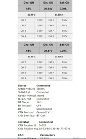
Seems ur invertor send only one time the reg 0x305 , after some time if nothing is received the interface will write Invertor disconnected
This is only for info not make any change , the interface will continue to send CAN data even if aperar Invertor disconnect

Other invertors like Victron send also 0x305 but resend every 2s.

Thell me if Li protocol work better on deye then pylon ?

The difference is in LI no reg with name is send it , also the reg for errors and warnings is different.

When are 2 batteries
SOC is calculated (SOC1 +SOC2)/2
Nominal Capacity = n1+n2
Remain Capacity = r1+r2
Warnings / Alarms = w1 xor w2

Li-LV gives no information to the inverter. Pylon only works like every 5th restart, Seplos works every restart.

The serial interface of the second BMS doesn't send correct information, the RS485 module in it is faulty, but I haven't had the chance to get it replaced under warranty yet. BT has no issues in the app at least, but doesn't play nice with ESP32.

Would it make more sense to try a RS485 protocol for Deye, instead of CAN? This is the list of supported protocols, that I have:
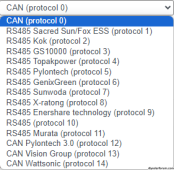
protocols.png
With CAN, the only decent response I get is from protocol 0 and mostly with Seplos. Tried Li-LV with both protocol 0 and 14 multiple times, no response from the inverter. I'll try with just the serial connection and Li-LV tomorrow as well, maybe it's the BT connection or the second BMS that causes issues.
 
Không, bạn không cần bất kỳ jkbms nào, chỉ cần cắm Esp32 vào máy tính và flash nó, sau khi mở Console trên cổng USB 8N1 115200, bạn cần nhận được:
Tôi sẽ tải lên một bản tổng hợp với bảng Wroom

Code:
ets Ngày 29 tháng 7 năm 2019 12:21:46

đầu tiên:0x1 (POWERON_RESET),khởi động:0x17 (SPI_FAST_FLASH_BOOT)
cấu hình: 0, SPIWP:0xee
clk_drv:0x00,q_drv:0x00,d_drv:0x00,cs0_drv:0x00,hd_drv:0x00,wp_drv:0x00
modeIO, div đồng hồ:1
tải:0x3fff0030,len:1344
tải: 0x40078000, len: 13924
ho 0 lô 12 phòng 4
tải: 0x40080400, len: 3600
mục 0x400805f0
Cơ quan giám sát BMS V 4.0
Khởi động
Đang gắn FS...
Hệ thống tập tin được gắn kết
Đọc file cấu hình
Đã mở file config, size = 142
Kết nối giao thức tiếp theo 1
Giao thức BT 0
Có thể Giao thức 1
Thiết bị ID đã được sử dụng
*wm:Tự động kết nối
*wm:Đang kết nối với AP ĐÃ LƯU: STF
*wm:connectTimeout chưa được cài đặt, ESP waitForConnectResult...
*wm:Tự động kết nối: THẤT BẠI
*wm:StartAP với SSID: JkBMS
*wm: Địa chỉ IP AP: 192.168.4.1
*wm:Bắt đầu cổng thông tin web
Chạy cấu hình
CÓ THỂ cài đặt thành công...
CAN Driver khởi động thành công...
Cấu hình Jk Connection
Can you explain this part clearly? Where to put it in parameters? I'm new to esp so I don't know yet. please help.
 
I uploaded 4 files as you instructed but I don't see the esp transmitting wifi to the address 192.xxx.xx.xx as you instructed.
Have you connected to the Wifi network created by the ESP32? You'll need to connect to it, then enter your Wifi network credentials. After that your router will assign an IP address to the ESP32, then you can access it with that address.
The 192.168.4.1 only works within the ESP32 Wifi network, the local router will probably assign a different IP address for the device. For example, for me it's 192.168.31.43. It will show up in your router as JKBms, so should be rather easy to find.
 
Bạn đã kết nối với mạng Wifi do ESP32 tạo chưa? Bạn sẽ cần kết nối với nó, sau đó nhập thông tin xác thực mạng Wifi của mình. Sau đó, bộ định tuyến của bạn sẽ gán địa chỉ IP cho ESP32, sau đó bạn có thể truy cập nó bằng địa chỉ đó.
192.168.4.1 chỉ hoạt động trong mạng Wifi ESP32, bộ định tuyến cục bộ có thể sẽ chỉ định một địa chỉ IP khác cho thiết bị. Ví dụ: đối với tôi đó là 192.168.31.43. Nó sẽ hiển thị trong bộ định tuyến của bạn dưới dạng JKBms, vì vậy sẽ khá dễ tìm.


I understand connecting to the wifi that the esp 82666 emits. but no wifi was found. I used 2 phones and it still can't be found. Can you tell me which files I need to upload? I'm thinking I'm uploading the wrong file. Please circle or show me the name of the file to upload
 
I understand connecting to the wifi that the esp 82666 emits. but no wifi was found. I used 2 phones and it still can't be found. Can you tell me which files I need to upload? I'm thinking I'm uploading the wrong file. Please circle or show me the name of the file to upload
Post #49 in this thread has all the settings and information that you need (the second image with bootloader and partition). And if it still doesn't work, make sure you are flashing the ESP32 correctly.
 
I understand connecting to the wifi that the esp 82666 emits. but no wifi was found. I used 2 phones and it still can't be found. Can you tell me which files I need to upload? I'm thinking I'm uploading the wrong file. Please circle or show me the name of the file to upload
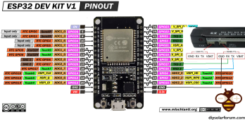
The soft work only with ESP32 !!!!
ESP32-DOIT-DEV-KIT-v1-pinout-mischianti.png


U have esp8266 so dont work with ur board!
 
Exactly, only when both batteries are connectors. When it is UART only, everything is correct. The Ah number is also correct on both, it's just the SOC that's messed up on UART when both are connected.
I upload deye protocol on interface. also documentation, is similar with Pylon , only the Name is different, inverter need to replay every 1 sec with 0x305.
 
I upload deye protocol on interface. also documentation, is similar with Pylon , only the Name is different, inverter need to replay every 1 sec with 0x305.
Seems to work better, it connects every time I restart and is a lot faster with BT connected, the SOC issue is fixed as well. However it still seems to drop the connection to the inverter after 25-35 minutes, even with just 1 BMS connected. For some reason, when 2 BMSs are connected (serial and BT), the software restart does not reconnect with the inverter, it needs to be physically rebooted with the EN button. With just the serial connection, software restart reconnects with the inverter.
On the inverter, under the BMS page, it still only shows the current from just the serial connection, both with 1 or 2 BMSs connected.

EDIT: Seems if I set the CAN interface to DUAL CAN, the connection stays active. It's been active for 3 hours straight already, so a lot better then previously.
 
Last edited:
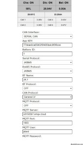
V5_config.jpg

I add the freeware with 2 serial connections and also with mqqt tcp connection.
after few tests i think the is cause by the BT connection, when u use bt + serial connection + http portal the delay for CAN msg send is more then 1S and invertor make an error with can comm problem.

Also after i add mqqt lib if the server not responds will be some lag, so if u want u can test it.

In mqqt i add only the can msg not all battery.

I test deye invertor with no comm error on serial.

V5_config2.jpg
 
I followed this block with great interest.I use a Sungrow SH10 RT, my DIY HV block with DALY Smart BMS 48 S doesn't work yet.Is it correct that I can connect my system with the small solution, 1 Can Port?
thanks in advance
 
Hello Mr. Constantin, after further consideration, I would convert my battery block to 66S and three JK BMS.
Can you help me configure the interface?
Hi,

U want to connect to Sangrow RT10 HV

Do u all ready buy daly 48s? if yes just use it dont spent more money , i will provide some soft for it.

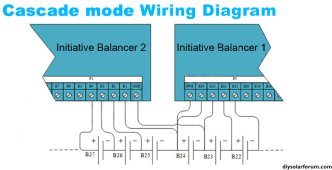
For HV i describe if u use jk u need jk balancers not jkbms ! Becose u will need more then 1 and if u connect in series u will not have same gnd for serial port!!!!

72a302e8-6823-4193-9d71-e80cc0cdcf85.jpg

Also will need 2 CAN Port 1 to read balancer other to invertor

If u need more details write to me.
 
Hi,

U want to connect to Sangrow RT10 HV

Do u all ready buy daly 48s? if yes just use it dont spent more money , i will provide some soft for it.

For HV i describe if u use jk u need jk balancers not jkbms ! Becose u will need more then 1 and if u connect in series u will not have same gnd for serial port!!!!

View attachment 172835

Also will need 2 CAN Port 1 to read balancer other to invertor

If u need more details write to me.
Hey,

My batterypack (48s) is already connected with the inverter. i had tested CAN and RS458 already and it didnt work. the easy way would be to connect this block. But i would like to have the full 66s. I would like to buy and use 3 JK acitve balancers and wire them. how would the CAN connection between the devices look like?
 
Back
Top