svTrouble
New Member
I’m hoping someone can help me figure out a problem that has been vexing us for about a year now.
The Problem
Since we’ve cruising we haven’t been able to get our house batteries over about 13.5 volts. Well, when the engine is on it gets to about 13.85, but drops down to 13.5 when we turn the engine off. Once the batteries get to about 13.85 the charge flattens out and no matter how long we run the alternator, it doesn’t get higher.
The Situation
We live on a sailboat that we’ve been cruising on for a year, which means we’ve been far away from shore power. About 2 and a half years ago we partnered with a ABYC-certified electrician and redid a good portion of our electrical system. This included:
Our Loads
We only use our inverter to boil water for coffee in the morning. Starlink is on for 2-4 hours a day. We do have a very efficient cooler and a 45-quart Engel freezer that is set conservatively. And we run a water maker every three days.
Some possible clues
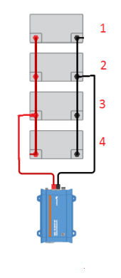
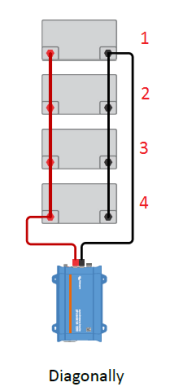
Our house bank is divided into 4 and 2 (due to space). The batteries in each group have very short wires connecting them, but the groups have a span that is probably 4 to 4 1/2 feet between them. The electrician said that this isn’t ideal, but shouldn’t be a problem.
The alternator has a 300A fuse on the positive side (https://www.bluesea.com/products/5190/MRBF_Terminal_Fuse_-_300A). When the engine is on this fuse gets hot: 260F to 300F. The wire connecting this fuse to the busbar is around 100F, and the temp on the alternator side is even less.
The house bank uses a 200 amp 187-series circuit breaker (https://www.bluesea.com/products/7149/187-Series_Circuit_Breaker_-_Surface_Mount_200A). A friend suggested that this isn’t adequate, and we should be using a class t fuse, with a higher capacity.
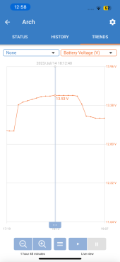
Attached is an example of a charging curve over an hour. You’ll notice that in the first 30 minutes, it goes from 13.40v to 13.53, and then it flattens out. It even goes back down to 13.53 at the end.
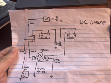
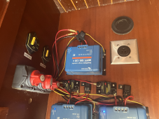
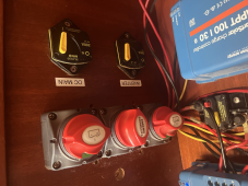
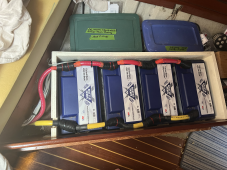
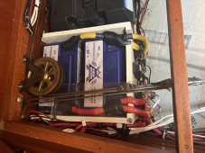
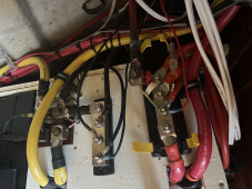
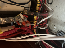
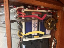
Attached you will see our wiring diagram and some photos of the installation
Conclusion
I can supply any further information I can include that would help diagnose this issue. We are so tired of running our engine for an hour every day, maybe two if we get good sun. We are just wasting diesel.
We are currently in remote Baja and have limited access to parts and resources.
We are desperate. If you have any suggestions or tests we should run... If you have a remote electrician you'd suggest to figure this out we'd be happy to pay someone who knows can figure this out.
Thank you for your time.
The Problem
Since we’ve cruising we haven’t been able to get our house batteries over about 13.5 volts. Well, when the engine is on it gets to about 13.85, but drops down to 13.5 when we turn the engine off. Once the batteries get to about 13.85 the charge flattens out and no matter how long we run the alternator, it doesn’t get higher.
The Situation
We live on a sailboat that we’ve been cruising on for a year, which means we’ve been far away from shore power. About 2 and a half years ago we partnered with a ABYC-certified electrician and redid a good portion of our electrical system. This included:
- 6 100 amp hour Battleborn LifePO4 batteries.
- A Balmar 94 series 210 amp high output alternator
- note: We have a separate alternator to charge starting bank.
- note2: The alternator charge controller is programmed for these particular batteries
- A Xantrex freedom 3000w inverter
- New wiring, a new panel, fuses, switches, etc.
Our Loads
We only use our inverter to boil water for coffee in the morning. Starlink is on for 2-4 hours a day. We do have a very efficient cooler and a 45-quart Engel freezer that is set conservatively. And we run a water maker every three days.
Some possible clues
Our house bank is divided into 4 and 2 (due to space). The batteries in each group have very short wires connecting them, but the groups have a span that is probably 4 to 4 1/2 feet between them. The electrician said that this isn’t ideal, but shouldn’t be a problem.
The alternator has a 300A fuse on the positive side (https://www.bluesea.com/products/5190/MRBF_Terminal_Fuse_-_300A). When the engine is on this fuse gets hot: 260F to 300F. The wire connecting this fuse to the busbar is around 100F, and the temp on the alternator side is even less.
The house bank uses a 200 amp 187-series circuit breaker (https://www.bluesea.com/products/7149/187-Series_Circuit_Breaker_-_Surface_Mount_200A). A friend suggested that this isn’t adequate, and we should be using a class t fuse, with a higher capacity.
Attached is an example of a charging curve over an hour. You’ll notice that in the first 30 minutes, it goes from 13.40v to 13.53, and then it flattens out. It even goes back down to 13.53 at the end.
Attached you will see our wiring diagram and some photos of the installation
Conclusion
I can supply any further information I can include that would help diagnose this issue. We are so tired of running our engine for an hour every day, maybe two if we get good sun. We are just wasting diesel.
We are currently in remote Baja and have limited access to parts and resources.
We are desperate. If you have any suggestions or tests we should run... If you have a remote electrician you'd suggest to figure this out we'd be happy to pay someone who knows can figure this out.
Thank you for your time.