diy solar

diy solar

Capacity test Eve 304 ah 3.2 volt battery 16 cells

gian83

New Member
Joined
Mar 25, 2023
Messages
76
Location
33143
HI to everyone
Found Some Grade A EVE Lipo4 cells 304ah 3,2v in Huston area for 143 dollars each and i bought 16 cells to build the battery with JDB 200amp bms.

Initial check with meter shows 3.29v on all of them .

Looking to do a capacity test by discharging and charging the battery bank.

I think after look some videos the recommended safe charge voltage is between 3.5 and 3.6 volt for this cells correct?

My question is about the discharge voltage i should use and is it safe to discharge the battery completely or should i stop when they reach 20% ?

Any suggestion on a affordable charger i could use to charge those battery fast or a safe tools to test the capacity without blowing the cells.

Thanks
 
If you want to do a capacity test of the whole battery (i.e., all 16 cells connected with a BMS, etc.), you really have to do a top balance first. Information here. The reason is that if you just hook them up as-is, they're likely not at the same SOC and you'll end up getting results that look like your battery has much less capacity than it actually does, or can if it's balanced.
So for a TEST (note, I wouldn't operate like this, it's only for a capacity test):
  • Top balance the cells.
  • Assemble the cells into a battery with a BMS (do not do this without a BMS!)
  • Charge the battery until one cell reaches 3.65V (max 'safe' voltage). Your BMS will do this if you set it up correctly.
  • Do the discharge test - use a tester or run a load through an inverter, making sure you have a way to measure the capacity. Testers will do this automatically, but if you're just running a load you'll need a shunt or some other way to measure Ah. Stop the test when one cell reaches 2.5V (min safe voltage). Again, your BMS will do this part automatically if set up correctly.
  • Charge the battery back up, at least partially. I don't like leaving these cells at 0%.
For normal operation, 2.5V to 3.65V is too large of a range. Lots of opinions on this site, but the 2.9V to 3.5V range will capture well over 90% of your usable capacity without risking shortening life.

Any suggestion on a affordable charger i could use to charge those battery fast
If you're charging as a whole battery, use whatever you plan to charge them with in operation... Many/most inverters can charge from mains power. I don't know of a lot of other 'affordable' chargers for 48V systems, but maybe others on the forum do.
or a safe tools to test the capacity without blowing the cells.
Use the BMS, its job is to protect the cells. Or, test the cells individually with a ZKE tester, they can be set up to charge and discharge to specific voltages and do a very good job. Limited usefulness aside from testing individual cells though.
 
i
  • Charge the battery until one cell reaches 3.65V (max 'safe' voltage). Your BMS will do this if you set it up correctly.
  • Do the discharge test - use a tester or run a load through an inverter, making sure you have a way to measure the capacity. Testers will do this automatically, but if you're just running a load you'll need a shunt or some other way to measure Ah. Stop the test when one cell reaches 2.5V (min safe voltage). Again, your BMS will do this part automatically if set up correctly.
Thanks for the help.

I have to install eg4 6500ex inverter soon but weather doesnt help as i have to install solar panels on the roof as soon it stop raining.

Question for you. Does the bms need to connected with the Inverter or charger in order to stop the voltage for damaging the cells ? Or it just stop the current from reaching the cells even its not communicating with the inverter or charger?
 
Does the bms need to connected with the Inverter or charger in order to stop the voltage for damaging the cells ?
The BMS will stop the current by opening the contactor or the MOSFETs. It does not need to communicate with the inverter or charger to do that assuming the BMS is wired between the battery and the inverter/charger. You still need to set appropriate charging and discharging parameters on the inverter/charger to stop at the correct voltages.
 
The BMS will stop the current by opening the contactor or the MOSFETs. It does not need to communicate with the inverter or charger to do that assuming the BMS is wired between the battery and the inverter/charger. You still need to set appropriate charging and discharging parameters on the inverter/charger to stop at the correct voltages.

Good to know that i was concerned about it thanks for the info. I'm building my first battery bank with 16 cells total of 304ah 51.2 volts and in the future i would need to parallel them with another bank same size. I just read that parallel two battery strings its not recommended but there is no way to connect 60kwh battery to two inverter without parallel them. Do you know what type of contactor that automatically disconnects the string in the event of a failure beside using two bms?
 
I just read that parallel two battery strings its not recommended but there is no way to connect 60kwh battery to two inverter without parallel them.
Opinions vary about paralleling batteries and cells. In my opinion, it is a matter of personal preference, except in the case of a manufactured battery with a self contained BMS and which the Manufacterer does not recomend paralleling them. I have a 3P16S pack with one BMS.
Do you know what type of contactor that automatically disconnects the string in the event of a failure beside using two bms?
I have a 200 Amp JBD BMS with a contactor, Does yours have a Contactor? You have choices. Assuming the new cells are the same, you can parallel each pair of cells into a 2P16S pack and use one BMS, feeding a bus bar connected to both inverters. Or you can buy another BMS and have two 1P16S packs with separate BMSs wired to a common bus bar feeding two inverters. The advantage is you can remove one pack for maintenance and have your system still run. The disadvantage is more complexity. A third option is to have each battery pack connected to each inverter but that is not optimal because one may discharge faster or more deeply than the other.
 
Opinions vary about paralleling batteries and cells. In my opinion, it is a matter of personal preference, except in the case of a manufactured battery with a self contained BMS and which the Manufacterer does not recomend paralleling them. I have a 3P16S pack with one BMS.

I have a 200 Amp JBD BMS with a contactor, Does yours have a Contactor? You have choices. Assuming the new cells are the same, you can parallel each pair of cells into a 2P16S pack and use one BMS, feeding a bus bar connected to both inverters. Or you can buy another BMS and have two 1P16S packs with separate BMSs wired to a common bus bar feeding two inverters. The advantage is you can remove one pack for maintenance and have your system still run. The disadvantage is more complexity. A third option is to have each battery pack connected to each inverter but that is not optimal because one may discharge faster or more deeply than the other.
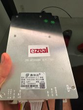
I think we have the same BMS JBD ap20s006 200a

WhatsApp Image 2023-03-30 at 4.36.25 PM.jpeg

If i understand this correctly you have one bms connected with 48 cells making one battery .But going so you only can monitor 16 cells .
So i think you balanced them first , test them and put them at the same state of charge and connected them together.
I was thinking to buy bms of each 16 cells battery string but maybe with your method i can save some money

do you know if multiple bms like this one can be connected togheter and communicate ?
 
Last edited:
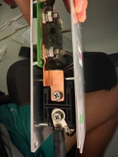
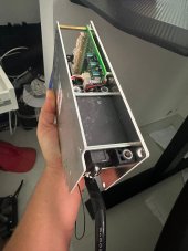
We may have a different BMS. Mine definitely has a contactor. I cannot tell about yours unless I see a side view that shows the contactor.
To clarify my JBD is used on a pack that runs a 32 volt chipper shredder and uses Nissan Leaf Modules.

The pack in my signature is an Orion BMS that manages my 3P16S house pack that supports my SolArk I am not sure what you mean by only monitoring 16 cells? I monitor the pack which appears as 16 cells because each buddy group of three cells electrically appear as once cell. As I said earlier, there are pros and cons of doing it that way or having three individual packs with separate BMSs for each pack.
 
We may have a different BMS. Mine definitely has a contactor. I cannot tell about yours unless I see a side view that shows the contactor.
To clarify my JBD is used on a pack that runs a 32 volt chipper shredder and uses Nissan Leaf Modules.
WhatsApp Image 2023-03-30 at 5.10.32 PM.jpegWhatsApp Image 2023-03-30 at 5.10.27 PM.jpeg
 
The pack in my signature is an Orion BMS that manages my 3P16S house pack that supports my SolArk I am not sure what you mean by only monitoring 16 cells? I monitor the pack which appears as 16 cells because each buddy group of three cells electrically appear as once cell. As I said earlier, there are pros and cons of doing it that way or having three individual packs with separate BMSs for each pack.
If You Can share the model of the bms or a link where to buy the orion bms bc you connection with the cells might work for me too.
putting to many bms might very hard to monitor without the bms communicating with the inverter .
I rather connect as many cells as i can together using one bms .My goal its 60 kwh battery bank
 
Yes that is a contactor based BMS just like the one I have. It should work fine for starters until you find one that will communicate with your EG4.
There is a thread somewhere on this forum where someone found a BMS that works with the EG4. If I find it I will post a link. EDIT: I found one thread where someone was trying to replace the BMS in an EG4 battery and he had no luck finding a BMS that would communicate with the EG4 inverter. That does not mean there is not one, just that I don't have any information because I am not familiar with the EG4.

My Orion BMS JR costs around $600 and I have no idea if it will work with the EG4. I have a SolArk and the SolArk inverter and the Orion are able to use a Victron protocol which the Orion can be set for. If you find that the EG4 inverter will work with an Orion BMS JR I can send you some links to vendors I have used.
 
Last edited:
Back
Top