diy solar

diy solar

Chargery BMS now with Low Temp Cutoff

Jason, can you describe why 11V and not lower? As common LVD values are in the range of 2.5 - 2.9V, I'd really like to be sure that the Chargery unit would be safe and reliable with battery voltages down to at least 10V for my 4S configuration. I am not driving high current relays with the Chargery unit--maximum total current pulled from the Charge Enabled and Discharge Enabled lines will be less than 100mV

Following is from member Cal in other thread. Can you comment?
Cal is correct, when battery voltage is 10V, BMS can still be work, but LCD back light will be dark than at 12V, and Beeper will be deep. the charger relay and discharge relay don't be cut off or turn on reliability. so 10V power BMS is not suggested.
 
And a follow up question.

Is the Chargery capable of measuring amps with better resolution ?

Now it seems that it only does whole numbers like 1 amp or 2 amps. Can it measure 1.2 amps or 1.8 amps for example.

Tenths of an amp would be very helpful. Especially if it can be enabled in firmware.
with 100A 75mV shunt and measure current under 100A, if the accuracy is 1%, so 1A, 2A should be accurate after calibrated, but 0.1A must be estimated, 0.1A means 0.075mV on shunt, it is too small.
with 10A 75mV shunt and measure 10A current, 0.1A means 0.75mV on shunt, so 0.1A should be accurate after calibrated.
 
Cal is correct, when battery voltage is 10V, BMS can still be work, but LCD back light will be dark than at 12V, and Beeper will be deep. the charger relay and discharge relay don't be cut off or turn on reliability. so 10V power BMS is not suggested.
Thanks Jason. If the charge and discharge relays cannot be reliably controlled at 10V then clearly I will not want to use it there. Just to confirm, above 11V the BMS operation including control of relays will be reliable? If so, then the minimum LVC value that will be reliable is 2.75V.
 
with 100A 75mV shunt and measure current under 100A, if the accuracy is 1%, so 1A, 2A should be accurate after calibrated, but 0.1A must be estimated, 0.1A means 0.075mV on shunt, it is too small.
with 10A 75mV shunt and measure 10A current, 0.1A means 0.75mV on shunt, so 0.1A should be accurate after calibrated.
Could you consider extending resolution to 0.1A even for the higher current shunts? It is understood that higher resolution does not mean higher absolute accuracy. But it would be useful to have that additional digit of resolution to be able to observe smaller relative variation.
 
ye
Thanks Jason. If the charge and discharge relays cannot be reliably controlled at 10V then clearly I will not want to use it there. Just to confirm, above 11V the BMS operation including control of relays will be reliable? If so, then the minimum LVC value that will be reliable is 2.75V.
yes, please measure relay controller voltage when battery voltage is 11V, the relay controller voltage must be over 9.6V , other wise don't cut off reliably.
 
Hi Jason, thanks for joining the forum, it's great to have the designer here. I'm new here and also just bought a Chargery BMS8T that I have just started turning on and testing.

I have a question on the current sensing input. There seems to be an issue with inverter-caused ripple current. I will summarize here a discussion on another Chargery thread.

Issue: The Chargery current display cannot handle inverter-caused current ripple--possibly due to lack of ADC input filtering

Test setup: 2000W inverter driving a ~300W incandascent lamp (pure resistive load)

Observations:
- Measured steady 21A DC on 12V input to inverter using both Victron BMV-712 and a Blue Sea clamp DC/AC ammeter set to DC amps
- Chargery current meter varied between 17A and 27A with a 7 second period
- Blue Sea clamp meter measured ~6A AC current on the 12V input to the inverter. Don't know the frequency as I don't yet have a scope.
- Another member "Cal" on this forum posted a scope trace measured at the shunt showing large 120Hz ripple.

Hypothesis: The Chargery current sense input appears to have an ADC without an input anti-alias filter than can reject the 120Hz ripple before sampling. So with a sample rate (update rate of current display) lower than the 120Hz ripple, it aliases, resulting in the slow, large current variation I observed.

Possible solutions:
- Software: I don't believe this can be fixed in software, as the aliasing can result in very slow variation, all the way down to DC, and can't be filtered after the fact.
- Hardware: Could insert a lowpass filter that can reject 120Hz in the current sense lines, to act as an input anti-alias filter. For example, a 10k series resistor followed by a 2.2uF shunt capacitor would have a corner frequency of about 7Hz and provide about 24dB of rejection on the ripple. Or maybe an LC 120Hz notch filter for more rejection.

Questions:
1) What does the input circuit for the current sense lines look like? Is it high impedance?
2) Do you see any issues with adding a filter on the current sense input as described above? Any suggestions?
3) What is the update rate of the Amps display?

Any comments you have on how to address this ripple issue and get a stable Amps display on the Chargery unit with an inverter in the system would be appreciated.
answers for 3 questions.
1)the input circuit for the current sense is high impedance
2) add a lowpass filter such as 10K resistor followed by a 2.2uF maybe cause a delay, the current changes don't be detected quickly by BMS. on BMS8T, can add two resistors between shunt and current sensor wire (red and black), replace C82 and C86 with 2.2uF capacitor. if need, please calibrate again.
3) it is 1Hz
Thanks for the answers, much appreciated. I will try this and see how it does in reducing the displayed ripple. I think the filter delay will not be an issue. The time constant of this filter will be about 22ms. I'm not aware of any real-time response required from a BMS in that short of time. The battery state changes slowly even if current does fluctuate quickly. And a filter is linear so it should not affect the accuracy of the BMS estimate of Ah or SOC.
 
i have my 8T hooked up the bench at the moment, testing with inverter (4S pack, no external v source)
what i notice is that when i fire up the inverter and draw 1500W, the current sensed by the 8T bounces around (as noticed), but what i don't see is the kwh changing - it's sits at 000, the % changes at the top of the screen as the pack voltage changes
when i charge with 5A supply it counts kwh properly?
 
For whatever reason, kwh display does not go negative. You need to fully charge the battery first. kwh will now decrease when using inverter.
 
Hello,

as promised the source of Chargery BMS driver for the Venus OS devices: https://github.com/Tobi177/venus-chargerybms

I will add more documentation if I will find more time.

Bye
Tobi

Thats awesome stuff Tobi17!!
I have already adjusted the QML to suit my raspberry pi venus device and am now going through the code to change it to ttyUSB1 as there is a victron SmartSolar 150/35 sitting on TTYUSB0

This seals it for me, I get a chargery now, no paying for big bucks Batrium (as much as their system is cool!) :)

Also good to see Jason in the forum, the designer of the Chargery devices.

Cheers
Ben
 
I have been up all night working on the driver that Tobi17 produced. he gave me a big head start. It needed a few tweaks though:

It needed an installer
it was hardcoded to ttyUSB0 - there may be more than one device connected to the venus device, so not quite plug and play. It may not find itself on ttyUSB0, so the driver will be looking there, yet the device is on some other port, such as ttyUSB1,2 etc.

To fix plug and play, I added some code so when it is pugged in, it creates a copy of itself on ttyCHG1, so no matter if it appears on ttyUSB0 or ttyUSB99, it'll still appear on ttyCHG1 (stands for Chargery port 1). I then changed the driver and qml pages to reference this port. Boom! Plug and Play :)

The installer I made is a simple bach script. It:
copies the files and folders into the right place
adds the required lines to some configuration files
adds the magic that creates the symbolic link to ttyCHG1 from whatever port it appears on.

All one needs to do is load up windows, use FT_PROG to reprogram an FT232RL device to have a name of "CHARGERY BMS" and flip on TX inversion and they are good to go.

Changing the model name of the device still allows it to be used with windows or other computer (like my mac). This avoids having to edit inf files or kexts etc to get the device to be able to be used as a normal FT232RL device or for simply troubleshooting the cable/bms's serial port before connecting to the venus device.

Will git hub it later. as I said, I've been up all night and need to get some sleep the collaborate with Tobi17, to pass on my additions, and be added to his github as a contributer.
 
Just makes it easier for people with a Victron monitor to enable the Chargery info on the Victron device's screen. Tobi17's driver bring a third, and most importantly, affordable BMS to the table for Victron users (the other two, Batrium and REC are outlandishly expensive).

Of course with this, events can be acted on by the chargery or the victron equipment to make the off grid installation run like a swiss watch, and be able to monitor it from anywhere on the planet. :)
 
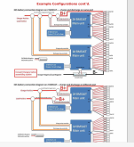
Hello Gents, I finally decide two go the route of the picture attach from the chargery manual edited by Steve great work.
my questions or confusion it state contact chargery as to why?
question 2 i see two different setup what is the advantage or disadvantage?
my system so far dual magnum inverter 4448pae, magnum pt100, magnum shunt aka battery monitor and 32 calb lifepo4 battery
please feedback and help me to close my remaining confusions
 

Attachments

  • Annotation 2020-05-23 113451.png
    Annotation 2020-05-23 113451.png
    457.5 KB · Views: 38
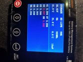
each cells close enough? are they balanced?
 

Attachments

  • IMG_20200525_204216_resized_20200525_084435945.jpg
    IMG_20200525_204216_resized_20200525_084435945.jpg
    59.7 KB · Views: 25
@Chargery
Hello and thanks for joining the forum. I have a questions. Why is the current display so inaccurate, i.e. without a decimal place? I know that it was not originally intended for solar applications. Could you maybe improve that with a firmware update?
 
@Chargery
Hello and thanks for joining the forum. I have a questions. Why is the current display so inaccurate, i.e. without a decimal place? I know that it was not originally intended for solar applications. Could you maybe improve that with a firmware update?
first the BMS detect the current shunt voltage when charge or discharge flow shunt, if shunt is 75mV 300A, when flow 10A, the voltage is 2.5mV, then BMS get 10A according to the voltage. if current is 1A, the voltage is 0.25mV, it is too small and affect the current detection accuracy because a tiny change such as 0.1mV, BMS get 0.35mV not 0.25mV. because of many factors affect the voltage detection, the voltage is not always stable. in theory it is 2.5mV, in fact it is not 2.5mV, may be 2.3mV or 2.7mV, and the current is not stable at the same time, BMS detect the voltage very quick to response to actual current change, so the current displayed is not stable or looks like inaccurate. it is non sense to display a decimal current.
use other device such as special current meter measure the same current, may be stable or looks accurate, but in fact, it is not accurate because it is average value, NOT instant current.
 
Is there any chance of a re-design and use a more accurate ADC? Can you tell us how many bits the ADC uses?

How often is current measured?
 
ye

yes, please measure relay controller voltage when battery voltage is 11V, the relay controller voltage must be over 9.6V , other wise don't cut off reliably.
Jason,
Looking at this again, is the 9.6V driven by the relay specs? I see that the coil operating voltage is 12V +/- 20%, which is 9.6V at the low end.

I am not using the Chargery relays—just SSRs and a small SPDT that pulls only 30mA. Based on that, can the BMS be safely operated to 10V, understanding that the backlight may be a bit dimmer?
 
Back
Top