diy solar

diy solar

Chargery BMS8T and BlueSea 7713 latching relay

greyghost

New Member
Joined
Feb 23, 2020
Messages
40
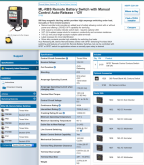
I'm wondering if anyone here has had personal experience with this combination. The 7713 consumes a mere 13mA when on, which is great. It also appears to have the correct outputs to operate this relay. However, I can't use the Cargery BMS with it if this BMS can't drive the relay.

Chargery indicates that max 2.5A is available on the Charge/Discharge relay circuit. BlueSea indicates this relay requires <7A to change state. It's not clear how much less than 7A will actually work, or work reliably.

Anyone have experience with these two?

Cheers,
Doug
7713 pic.png
 
I am not sure how latching relays work. The cahrgery outputs a 12V signal to turn a relay on. With a latching relay when the 12v is shut off will it open?

No, you need some electronics to drive the latching relay from a signal designed for a non-latching relay, nothing super complicated though.
 
Craig, these can be found for 60% of list price If one hunts around.

BiduleOhm, the coil is auto-releasing. I believe it will open the circuit when the voltage on its control terminals goes to zero, so when the bms control circuit is opened.

Doug
 
@Steve_S Your thoughts?
I have SSR's on the way but have not played with them at this stage, Craig is presently testing a few different ones, I dunno how many brands or models but he "got the SSR Testing Bug" (pretty good bug considering the times IMO). Per Specs, the charger outputs 12V max 2.5A to close an NO Relay / Contactor and keeps voltage constant while closed. I don; know what "brand" of relay's that BlueSea is using, I am certain however that it is a high quality component as BlueSea doesn't sell any junk from what I have seen and I own bluesea products.

At present I am running with the usual Electro-Mech contactors as provided by Chargery, they are "ok" but not really suitable for energy storage in my opinion as they are quite wasteful. In an EV type application they are fine (Chargery BMS was designed with EV's in mind but very flexible across the board) because it's not in 7/24.

Possibly @Justin Laureltec from Bay Marine may have some insights on these relay's as I believe he sells them, he may be able to tell us what brand / manufacturer they hail from. TBH I am somewhat shocked at how wide a price range SSR's have for similar amperage devices. I do want to point out, that VAC SSR's are much less expensive than DC Only Relays and that is not unexpected, because DC requires demands much more heavy duty components. MIG Welders are DC and for a reason, DC welds contacts! This is the main reason why AC stuff like switches, breakers & what not melt with serious DC and you shouldn't use AC stuff with DC gear. So to answer a Ponderance someone may have, NO You cannot use a Single Phase AC SSR with heavy DC, it will weld itself into oblivion.
 
@greyghost looking at the Blue Sea wiring diagram, I see they show a 2A fuse supplying power to the SPDT switch. So the signal is low power. It must be drawing the 7A on Connection A.
 
I was trying to figure this out the other day for my boat and went with the stock chargery relay (400amp). They consume zero power since they are normally open. The issue is when the battery shuts off the discharge relay because it’s too low and the relay consumes a few apps to stay closed, I will have destroyed batteries. That said, I will probably have a sunken boat as well since there would not be any loads draining the solar charger battery besides a leak.

I found another solution on this forum somewhere for a latching relay with electronics built in, but it was only for 100a or so.

Anyone know how to reliably connect a latching relay to a chargery???
 
Last edited:
I was trying to figure this out the other day for my boat and went with the stock chargery relay (400amp). They consume zero power since they are normally open. The issue is when the battery shuts off the discharge relay because it’s too low and the relay consumes a few apps to stay closed, I will have destroyed batteries. That said, I will probably have a sunken boat as well since there would not be any loads draining the solar charger battery besides a leak.

I found another solution on this forum somewhere for a latching relay with electronics built in, but it was only for 100a or so.

Anyone know how to reliably connect a latching relay to a chargery???
A "normally closed" (NC) relay passes power when the relay is not energized. which is unlike a NC valve in piping ... which does not pass flow.
A "normally open" (NO) relay passes power when the relay is energized. which unlike a NO valve... which does pass flow.

The stock Chargery relays are NO relays - as this is the "fail safe" design. The Chargery energizes them to permit current to pass to loads and charge sources. So they are consuming a little bit of power all the time in normal operation. When a Chargery protection limit is triggered, the Chargery de-energizes the relay, and load/charge current is interrupted - and power consumption by the relay ceases.

Ditto for any BMS that uses relays.
 
Last edited:
I suspect the Chargery BMS will work well with the BlueSea 7713 latching relay, without the need for a SSR. The power to activate the latching mechanism comes from either of the two main power leads at the base of the 7713, so the 2.5A available on the Chargery's the control circuit should be more than enough to keep the internals happy. Looks like FedEx has resolved at least some of its China backlog, with my BMS now scheduled to arrive once again. Will post back with my results on its compatibility with the 7713 when I've had a chance to test.
 
A "normally closed" (NC) relay passes power when the relay is not energized. which is unlike a NC valve in piping ... which does not pass flow.
A "normally open" (NO) relay passes power when the relay is energized. which unlike a NO valve... which does pass flow.

The stock Chargery relays are NO relays - as this is the "fail safe" design. The Chargery energizes them to permit current to pass to loads and charge sources. So they are consuming a little bit of power all the time in normal operation. When a Chargery protection limit is triggered, the Chargery de-energizes the relay, and load/charge current is interrupted - and power consumption by the relay ceases.

Ditto for any BMS that uses relays.

I guess that's why they say the fastest way to learn something on the internet is to post the incorrect answer. That's news to me. I thought NO meant it was normally open unless energized and held closed with current. I'm coming from ZERO electrical knowledge, so this is unfortunate and I will be watching this thread for a better solution.
 
I guess that's why they say the fastest way to learn something on the internet is to post the incorrect answer. That's news to me. I thought NO meant it was normally open unless energized and held closed with current. I'm coming from ZERO electrical knowledge, so this is unfortunate and I will be watching this thread for a better solution.
Think of it this way, NO = Normally OFF, as a normal switch, when the relay get's the 12V from the BMS it flips it ON to pass electricity. The problem with the various relays, is they consumer power while they keep the circuits ON and two relays are required. SSR's (Solid State) use the least BUT they are quirky and for DC application quite expensive, thank goodness that is changing slowly). The second most efficient are the Energy Mizer types like the TE ones previously which can be bought on Ebay for around 40-50 USD (used). Different people are in process of testing various "flavours" of Relays but this is time consuming and costly too, hopefully within a month or so, we may be able to provide a list of suggested relays which are power savers suitable from Energy Storage.

* The default Relays offered by Charger were / are intended for use in an EV and so their power consumption is not much of an issue in that application. For energy storage systems though, these draw enough power that the "Vampire Effect" is an issue for systems as the draw adds up. Now if you get enough charging per day, the "total" power cost for the relays is replaced and is just an overhead "cost" but after a few days of no generation / charging it adds up.
 
Good reviews from the marine guru. And I checked with bluesea and they said it would work. https://shop.marinehowto.com/products/blue-sea-7713-ml-rbs-remote-battery-switch-wmanual-control-release-12v

Now the only problem is the cost. I can stomach one of these because it’s redundant in that it is manually override able in case my BMS craps out in an emergency and I need to start a 200 amp starter, but what is an inexpensive low power relay/ssr good for only 100 amps max for the charge side?
You don't need an SSR to carry 100 amps if you can live with any BMS event killing all connection to the battery. (charge and load go through the latching relay.
Just use the SSR to interrupt the load relay control BMS output wired to the control side of the blue sea latching relay. SSR's control side would be energized by the charge side relay output from Chargery BMS. I have this up and running on my battery.
 
The link above is dead and redirecting incorrectly?

https://shop.marinehowto.com/produc...te-battery-switch-wmanual-control-release-12v

The description also says this:

"IMPORTANT: LI-ION BMS NOTE: If your BMS pulls the relay contacts to ground, to operate a relay, then you will need to invert this signal in order to use the 7713"

Many BMS's operate the relay driver terminals by pulling to ground. The Orion is one that quickly comes to mind, but many others do the same. A normal 12V contactor, such as a Tyco EV200, can be operated by opening/closing the neg leg/side of the coil.

Unfortunately, the Blue Sea 7713 cannot be operated on the negative side, like a standard coil driven contactor. In order to operate the 7713, the red wire in the pig-tail harness needs +12V applied or removed.

Trying to operate the 7713, on the negative side, will not work like it will with an EV200 or similar. The 7713 gets is power to operate from the A or B studs and the small red wire in the harness is what makes or breaks (opens closes) the 7713.

Apply +12V to the 7713's red pig tail lead & the switch closes, remove +12V from the red pig tail lead and it opens.

Once the 7713 is closed, or open, the neg lead does nothing to change states. If your BMS pulls to ground to operate the NO/NC terminals then the 7713 will need a way to invert that signal and switch the +12V side as opposed to the -12V side.
 
Last edited:
I just picked up the previous model (there are 2 prior models that look identical) on the bay for 99$ shipped. I will report what I find with my chargery 8T in a few weeks.

You don't need an SSR to carry 100 amps if you can live with any BMS event killing all connection to the battery. (charge and load go through the latching relay.
Just use the SSR to interrupt the load relay control BMS output wired to the control side of the blue sea latching relay. SSR's control side would be energized by the charge side relay output from Chargery BMS. I have this up and running on my battery.

Please post more info on this, Include a photo and a product link for the ssr would be helpful. There are two load controls on the chargery (discharge and charge relays) so I don’t totally get your description.

Safety wise, I think using one relay may work for me OK, since I can manually override the relay to do an emergency engine start (and my charging loads are victron and are set up for lifepo4).
 
Note, I've since replaced the Bosch Cube relay with the SSR in the photo of my circuit diagram, but I wired the SSR to interrupt on the positive side of the load contactor relay control. If you do your manual disconnect on the negative side connection to the high current load contactor relay, that will work well. That is how mine is now wired.
The 5A SSR I bought is here: https://www.opto22.com/products/dc60s5 for $22. It draws .01A supposedly. (I didn't verify.). But the Bosch cube relay draws .15A.
photo-on-3-19-20-at-12-03-pm-jpg.9278

One more note: on the SSR, the terminals 1 = 30, 2 = 87, 3=86, 4=85. On a normal Bosch Cube relay, polarity or current direction doesn't matter. In the SSR, it seems to matter.
 
Just picked up two (7712 old model) on the ebay, one for charge and discharge. There is also the 7710 that has identical looking specs as well. Ebay has some of the older ones for sub-100$ now and then. FYI
Two of these is probably a gold standard for a chargery system methinks?
 
Just wondering if this actually went anywhere am trying to figure out the same thing as everyone else only I want to use this between my panels and my SCC
 
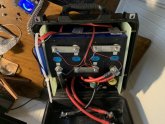
Works great. Will not function with just the control wires attached (in case you try to test it). It needs the + from the battery hooked up as well.
8B15BB7C-C110-4E47-8A36-FA28C439A49F.jpeg
 
Thanks man ok one more question I was planning on running 60v to my mppt as I am building a 24v system do you think this is up to the task
 
I don’t know enough to help you. The 24V version will work for 24 volts. If it’s running 60V it would not work.
 

diy solar

diy solar
Back
Top