diy solar

diy solar

Choosing the right ring terminal

_laurens

New Member
Joined
Oct 29, 2022
Messages
24
I recently bought a JK BMS but it required some crimping, I bought an hammer crimper and bought a set of ring terminals, but I'm not sure what to use for this.

The wire of the JK BMS is AWG7, my initial thought was the 'SC16-8' would be the correct fit for it but looking around awg 7 is 10.5mm +/- and I think because of that the 'SC10-8' must be used, but honestly it looks really small and the part where the wire goes through (tunnel) is rather small too.

What did you guys use to crimp this correctly? I'm a bit worried considering it's a 200A bms.
 
I'm a bit worried considering it's a 200A bms.
Not that i know anything about ring terminals but when i was shopping, i saw a comment/review from someone who appeared to know quite a bit. He said that the "UL Listed" ring terminals tended to be much higher quality with significantly more material that cheaper ones.
This was on Amazon. I got an assorted box of UL Listed ones (maybe 25-50% more expensive) and they did not disappoint.
I think it was money well spent.

Just my $.02
 
Is there such a thing as AWG 7? The standard says AWG6 is 16mm2 and AWG8 is 10mm2. There is neither AWG7, nor standard wire with cross-section between 10mm2 and 16mm2...

In any case - if the 10mm2 lug does not fit you should go for the 16mm2 lug. Or look for open-ended lugs and appropriate tool to crimp them.
 
it does fit in 10mm2 but barely with no space left; not sure if that would be the correct way to do it.

AWG 7 seems to be a thing, it's a awg that is not often used, likely. It's odd they included those wires; tbh I doubt it can pull 200amps both combined (I think they are alum wire)
 
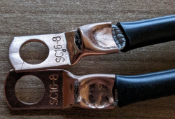
Thanks guys, did some test crimping, any tips?

I think the top one shifted a bit, would it be suggested to re-do that one? I used an hammer crimper.
Both are really stuck on it.
1669576644977.png
 
On the top one the wire stands are still poking through so I would suggest you have trimmed the insulation back a little far. Put some heat shrink on them and it makes it nice and neat but otherwise it doesn't really matter as long as the crimp is secure
 
Thanks, I will be sure to heat shrink them, was making sure if it was okay.
Will be sure to trim those loose hairs a bit, and apply heat shrink :)

Can't wait to receive my batteries!
 
the 7 AWG seems to be a weird size from what i can tell.

For my JK-BMS that also has the 7 AWG wire , i found that 10mm2 ring terminals did not fit, but the 16mm2 do fit. Now,im not sure how solid of a connection that would be and how much heat it will generate due to it not being a tight enough fitt.
Have you thought about putting a little solder in to fill up any gaps?
 
Please remember, AWG is purely an American thing.

And America is only about 2% of the entire world.
In Metric, 10 mm squared is a standard and very commonly used wire gauge throughout the entire World (since metrication).

And that falls very close to being half way between 6 AWG and 8 AWG.
So anything that size has become 7 AWG, (if you are an American).
Anywhere else its more properly called 10mm squared.
 
The school of thought seems to be that using solder is defeating the object of crimping esp where heat could be generated and melt the solder, better to not have any gaps to fill. Maybe fold to double the wire would be a better solution.
folding over the cable to get a tighter crimp is a trick i use too. thanks
 
If you are generating enough heat at the lug connection to melt solder (between 400°F / 200°C and 700°F / 370°C) then I would suggest that you have a very major problem.
indeed.

if the solder melts, you are already having a *very* bad day.

the crimp will hold the conductor in case the solder melts.

discouraging corrosion and reducing resistance are somewhat separate yet related goals. thanks
 
If you are generating enough heat at the lug connection to melt solder (between 400°F / 200°C and 700°F / 370°C) then I would suggest that you have a very major problem.
I agree and was a bad example for me to use, a better example might be the solder can crack with movement, but a good solid crimp will stay good. I have no problem with people using solder as I've used it on circuit boards for years. Just think a good fitting solid crimp is the best connection for wires.
 
First, crimp sizes are manufacturer specific, so you may find that some SC10-8 lugs from one manufacturer fit, while others form another manufacturer don't fit. So it's hard to recommend a size - other than to say find the one that matches the wire most closely but still goes in easily without stray wires.

Second, short chassis wires may be lower gauge than what your application needs, so if you're extending the wires then you should consider going to a larger wire size to suit your actual application. Not only for safety - which is critical, I'm not dismissing it - but for lower resistance and lower losses. 10mm2 wire is good for 60A in terms of energy loss and heating. Anything above 60A and you'll want to pay very careful attention to your wire selection and how it's routed - can the insulation take the heat? Is it going into conduit? What's the duty cycle for the high power? So if the BMS comes with undersized wires it might be ok depending on their specific wire, and the expected or required usage/installation their equipment requires. But you should transition to a larger gauge wire as close to the BMS as you can if you plan on pulling the full 200A rated current.

Third, you can't tell if a crimp is good or bad externally - you would need to cut across the crimp and look at the cross-section to verify the copper wire and ferrule contain no voids in the crimped area, or run the maximum power through it that it's expected to handle in cycles for a long period of time and confirm that it doesn't become hotter than the wire after all oxidation has taken place. If I had to guess, though, it looks like the crimp isn't completely solid, the SC16 is too large, and you have air gaps between the copper and portions of the ferrule. But again, it's possible that it's good - you just can't tell without destructive testing.
I just had a go at it yesterday with my 2 x JK BMS.
To be "ready" for all cases I purchased both the 10mm2 and 16mm2 cable lug.

After a bit of fiddling, the 10mm2 was "no freaking way". I could not even start pushing the JK BMS ultra-fine wire into it, not more than HALF would even accept to start going in :( .

So I had to go to with the 16mm2 cable lug. Afraid of not doing a "proper crimp" and also because the 16mm2 didn't seem to align very well when fitted on the hydraulic crimper, I went with the 10mm2 die set. And I went it all the way to 10 tons ... twice (2 crimps). Well 12-16 tons after the first hydraulic crimper started leaking and I had to switch to its bigger brother for 8-300 mm2 wires :rolleyes: ...

As a result quite big "wings" (maybe also called "ears" ?) formed, like this one on the left for instance (cannot comment on the text of this image, seems a bit weird especially the right one...):
1693110566243.png

Sometimes the wings came at 90°, but most came at 180° from each other. I guess in some cases the second crimp was angled compared to the first one.

I did NOT file or cut the wings off, as I didn't want to damage the crimp. Gave it a little tug test (pulled "reasonably", but without a "ton" of force :ROFLMAO:) and it didn't move. Just put heat shrink on it.

I have 2 x Smoke Detectors in that battery. I'm also considering glueing some temperature sensors on the cables and trip the system in case of overtemperature (shunt trip breaker, possibly also open contactor let's see). It's a bit more complicated than just the smoke detector though. Would need some Arduino Code / ESP32 to make use of the DS18B20 sensors

Any thoughts ? I know without destructive testing it's difficult to say. And destructive test when you wire is 10 cm to begin with is a bit hard ...

At that point if issues arise I would guess I would either:
- Replace the 10.5mm2 wires going to the BMS with something proper (e.g. 35 or 50mm2)
- Use terminal blocks WAGO 285-135 for 6-35 mm2 cables instead of cable lugs & busbars. NOT sure they would work very well with ultra fine (class 6) conductors though

EDIT: Image was on "Bad practices Examples" here: https://etechcomponents.com/crimping-common-mistakes-good-practice/
 
Last edited:
I was facing same issue as OP to find a terminal for AWG7. Ended up ordered from the following vendor on Ali. They aren't the cheap Chinese stuff at all. Specs / measurements are described in the listing. Pure copper thin.

The RNB14 is for AWG6-8. More important, all terminals are available with different sizes of bolthole from M4, M6, M8, M10, M12.

Also ordered some butt splice connectors.

Hopefully this might help someone.
 
Back
Top