diy solar

diy solar

Cinergi's 28 kWh / 4 kW Solar / 10 kW inverter RV build

I worked on solving the issue with the 2 groups of cells that had high resistance and high voltage fluctuations as seen by the BMS. I solved it, and I'm in shock.

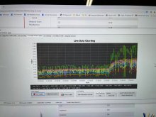
To recap - under load I would see about 4x the resistance between cell groups 4 and 5 (and between 12 and 13). It didn't show for the groups between 8 and 9 because the 9th group has its own negative BMS cell tap so the resistance between cells 8 and 9 don't get caught in the long cable joining the two. The BMS shows this as the yellow and green lines for cells 5 and 13:
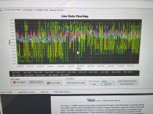
IMG_9197.JPG

This was causing the BMS to prematurely think that it was time to balance the cells, caused bad SoC corrections, and was providing erratic voltage readings for the entire battery (which was making the Quattro's constantly adjust the charging). I needed to solve this problem.

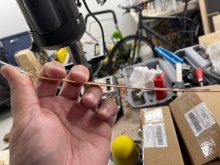
I tried using the Orion bus bar compensation feature (you manually add the resistance of the wire) which should correct for this -- but it didn't. I was having a hard time believing this could be skin effect, so my next attempt was to replace the two long 1 gauge cables with a single short 3/0 cable. No improvement. So, the only thing left to try was a bus bar. Fortunately I had the 1/4" by 1" tinned copper bars that I never really used and I notched out the wood and gave that a try between cell groups 4 and 5. I'm so grateful I have a drill press and chop saw now! That made this relatively easy:
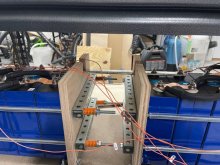
IMG_9215.JPG

and here's the result:

IMG_9216.JPG

I couldn't believe my eyes! The yellow line is with the others and the only outlier is the green line (cell 13). Here's a clearer view with just cells 4, 5, and 13 selected:
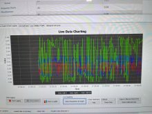
IMG_9218.JPG

OK, so 5 is a little higher than 4 -- which might seem expected but I measure half the resistance (half the voltage drop as seen by my meter) across that mammoth copper bar (it's more copper than 4/0), so I'm not sure what that's all about -- but it's quite clear that cell 13 is ridiculous. Here's the calculated resistances according to the Orion BMS - notice cell 13 is crazy high. Cell 5 is higher than the others -- which does not agree with my meter, so that's weird.
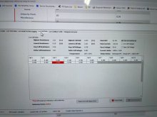
IMG_9217.JPG

So I replaced both connections - and here's my charge completing:
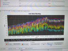
IMG_9219.JPG

SO much cleaner.

The downside of this is the physical stress that might be happening on the terminals while driving down the road. I'm now starting to contemplate going to groups of 16 and forgoing the individual mobility of each pack.

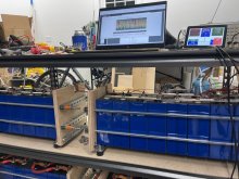
Given that the distance between the terminals is moving 0.2mm at most, I'm going to go back to solid bus bars (the same 1/4" by 1" stuff). I'm also ordering some 1/16" by 1" copper so I can attempt bending some copper in order to make the connections from the main battery positives and negatives to the contactor and circuit breaker rather than using wire (not due to the skin effect, but due to space constraints of trying to route the cables to the board directly to the right of the top and bottom rows of the battery, below).
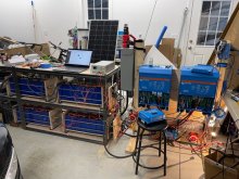

IMG_9196.JPG
 
After seeing the changes from moving to a solid bus bar between each group of 8, I decided to try using solid bus bars (1/4" by 1" copper) for the first 16 cells (which would easily compare against the second 16 cells given the BMS design). I've measured so little movement between terminals that I'm OK using solid bus bars. I wanted to see the difference.

IMG_9224.JPG

It's obviously a much cleaner look and it's a simpler install. I really like it. I like the single bars that cover 4 cells at a time. This will get converted into 2 16-cell packs using these rigid bus bars. My battery resistance as reported by Orion is now 1-2 milliohms instead of 3-4 ... I mean, the bus bars are rated for 400+ amps, so ... LOL ... WAY bigger than 4/0 cable which is 120mm^2 (it's somewhere between 300 and 350 MCM cable at 161mm^2).

I noticed some difference in the per-cell voltage swings during 140 amps of charge ... 25mv instead of 35mv. The cells with the bus bars were also ~10mv lower during that 140a charge -- meaning less resistance. (60% SoC) I was expecting a bigger difference since I'd removed the same cable that caused the huge skin-effect issues I previously documented. A little disappointing in that respect but that's OK. I like the cleanliness of the physical design. This will let me put nothing else on top of the bus bar but instead drill and tap dedicated holes in the bus bars for the BMS sense leads. I can use a single serrated nut on top and that'll make for a nice, easy, vibration-resistant design.

This makes for an insanely strong battery ... now we're talking about 38,000 available short circuit amps. It'll only get "worse" when I do the bottom row and when I make them 16-cell packs. I ordered everything I need to make that happen ... I'll document that in a later post, although I did get my 1/16" by 3/4" copper which will allow me to create the connections between main battery positive and negative to the contactor and circuit breaker really cleanly (I need to be able to bend this stuff .. I'll use 3 pieces in order to get 90mm^2 of copper which is about 3/0 cable. If I have enough left over, maybe 4 pieces which equates to 4/0. Cuz, you know, that's necessary. LOL.

IMG_9225.JPG
 
One cool feature I discovered due to the ability to use Victron Connect to configure the system now (it wasn't supported for multi-inverter systems) is "island mode" ... it doesn't connect to AC unless certain parameters are met. So what I'm doing is setting it to island (invert from batteries and solar) until it hits 10% SoC and then connects to AC and fully charges the batteries. This is letting me automatically cycle the entire 28kWh pack ... and my load is my current RV plugged into the 50A outlet I have wired to the Quattro's. So I'm not wasting energy - I'm just using my normal power from the RV until the batteries hit 10% and then they get charged up ... lather, rinse, repeat ... I'm cycling the pack every 24 hours or so right now! It's giving the system a great workout and proving out all the components, including the EVE 280Ah cells.
 
Hmmmm... is that an option in VEConfig?

Not that I remember and I poked around at it quite a bit. I'll have to check again because that would be crazy if this feature's been "hidden" as a result of not being able to use VE.Configure until now. Makes me wonder what other features I'm unaware of. I poked around quite a bit in Victron Connect, too -- didn't notice anything else... yet ..
 
Love this project. Thank you for the nice updates.
Where did you source the solid bus bars from?
 
Not that I remember and I poked around at it quite a bit. I'll have to check again because that would be crazy if this feature's been "hidden" as a result of not being able to use VE.Configure until now. Makes me wonder what other features I'm unaware of. I poked around quite a bit in Victron Connect, too -- didn't notice anything else... yet ..

Looks like it's time to enable demo library...

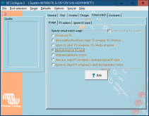
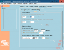
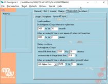
Ah. You calling it islanding had me looking for something too specific. In VictronConnect, it's AC input control. This function is configurable through VE.Config via Virtual Switches.

1614404449308.png

1614404476559.png

Thanks for the education! This is great!
 
Looks like it's time to enable demo library...

Ah. You calling it islanding had me looking for something too specific. In VictronConnect, it's AC input control. This function is configurable through VE.Config via Virtual Switches.

Thanks for the education! This is great!

Oh.. Virtual Switches.. I would never have thought it was in there.
You should be able to use Victron Connect now with yours.
 
Oh.. Virtual Switches.. I would never have thought it was in there.
You should be able to use Victron Connect now with yours.

Not as configured. My only way to access it is through the CCGX/VE.Bus. I don't have the dongle. I use VRM to download the config file, make changes as needed with VE.config, then upload the config file back to the Quattro via VRM.

If I'm missing something, clues are welcome.
 
Not as configured. My only way to access it is through the CCGX/VE.Bus. I don't have the dongle. I use VRM to download the config file, make changes as needed with VE.config, then upload the config file back to the Quattro via VRM.

If I'm missing something, clues are welcome.

Oh! I assumed you were using the MK3/USB dongle.
 
One cool feature I discovered due to the ability to use Victron Connect to configure the system now (it wasn't supported for multi-inverter systems) is "island mode" ... it doesn't connect to AC unless certain parameters are met. So what I'm doing is setting it to island (invert from batteries and solar) until it hits 10% SoC and then connects to AC and fully charges the batteries. This is letting me automatically cycle the entire 28kWh pack ... and my load is my current RV plugged into the 50A outlet I have wired to the Quattro's. So I'm not wasting energy - I'm just using my normal power from the RV until the batteries hit 10% and then they get charged up ... lather, rinse, repeat ... I'm cycling the pack every 24 hours or so right now! It's giving the system a great workout and proving out all the components, including the EVE 280Ah cells.
I use the Victron Multiplus "dedicated ignore AC input" option on my build too, however I don't charge the batteries all the way to full off of the grid. I charge from grid AC only if my battery SOC drops to 20% and I turn off the AC charge when my battery voltage reaches 26.96 V (on a 24 V system) for 5 minutes. This equates to a battery SOC of about 65% for my application. I shut off the AC charger at this level in order to leave headroom in the battery for solar input, allowing me to maximize my solar output. It works slick. If you charge your batteries all the way to 100% from the grid power, you risk having solar power available with no where to run unless you have some kind of other load sink capability. By the way I am enjoying watching you put your pack together. I'm a little envious. :)
 
Last edited:
I use the Victron Multiplus "dedicated ignore AC input" option on my build too, however I don't charge the batteries all the way to full off of the grid. I charge from grid AC only if my battery SOC drops to 20% and I turn off the AC charge when my battery voltage reaches 26.96 V (on a 24 V system) for 5 minutes. This equates to a battery SOC of about 65% for my application. I shut off the AC charger at this level in order to leave headroom in the battery for solar input, allowing me to maximize my solar output. It works slick. If you charge your batteries all the way to 100% from the grid power, you risk having solar power available with no where to run unless you have some kind of other load sink capability. By the way I am enjoying watching you put your pack together. I'm a little envious. :)

Quite true. I wish voltage-based charging was more accurate. I'd like to have it stop at a certain SoC instead. But this isn't how I'll actually deploy the system -- right now it's the method I'm using to forcibly cycle the entire pack and stress/prove the system.

I also wish I could tell it to prioritize Solar instead of shore while connected so that I'm not needlessly cycling my battery nor pulling from shore if there's enough solar.
 
Quite true. I wish voltage-based charging was more accurate. I'd like to have it stop at a certain SoC instead.
I agree. I'm not sure why Victron didn't make that an option to ignore AC input. It seems like it would be a simple software update.
I also wish I could tell it to prioritize Solar instead of shore while connected so that I'm not needlessly cycling my battery nor pulling from shore if there's enough solar.
I have found that I can accomplish prioritizing charging from my solar by setting lower absorption and float voltages on my Multiplus charger than what I have set for my solar charge controllers. I set my Multiplus charger to 27.0 V absorption and 27.0 V float, and then I set my solar charge controllers to 27.8 V absorption and 27.4 V float. The Multiplus settings are a bit academic since I normally ignore the AC input when my battery voltage reaches 26.96 V, but if for some reason I want to manually override the ignore AC settings, the solar controllers will continue to charge even after the Multiplus drops into float at 27.0 V. You might want to consider dropping your Quattro charger absorption and float voltage settings below your solar controller charge voltages to simulate the prioritizing that you want to do.
 
I agree. I'm not sure why Victron didn't make that an option to ignore AC input. It seems like it would be a simple software update.

I have found that I can accomplish prioritizing charging from my solar by setting lower absorption and float voltages on my Multiplus charger than what I have set for my solar charge controllers. I set my Multiplus charger to 27.0 V absorption and 27.0 V float, and then I set my solar charge controllers to 27.8 V absorption and 27.4 V float. The Multiplus settings are a bit academic since I normally ignore the AC input when my battery voltage reaches 26.96 V, but if for some reason I want to manually override the ignore AC settings, the solar controllers will continue to charge even after the Multiplus drops into float at 27.0 V. You might want to consider dropping your Quattro charger absorption and float voltage settings below your solar controller charge voltages to simulate the prioritizing that you want to do.

I have a CAN-BMS controlled system, so everything sends the same voltage. I can't control it without turning off CANBUS control :(
 
I have a CAN-BMS controlled system, so everything sends the same voltage. I can't control it without turning off CANBUS control :(
Looks like your left with the brute force method if you want to prioritize solar over grid charging. If you want to experiment, try setting the "ignore AC input" when the battery voltage reaches the equivalent of 53.92 V on a 48 V base (26.96 V on a 24 V base, as shown below) for more than 5 minutes. If its like mine, the AC input charging will drop off somewhere in the 60-65% battery SOC range. It's a pretty precise voltage setting in this part of the voltage curve. If I set mine only 0.02 V higher at 26.98 V, the AC input will charge my battery to about 85% SOC.

Ignore AC input setting for 65 percent SOC.jpg
 
Looks like your left with the brute force method if you want to prioritize solar over grid charging. If you want to experiment, try setting the "ignore AC input" when the battery voltage reaches the equivalent of 53.92 V on a 48 V base (26.96 V on a 24 V base, as shown below) for more than 5 minutes. If its like mine, the AC input charging will drop off somewhere in the 60-65% battery SOC range. It's a pretty precise voltage setting in this part of the voltage curve. If I set mine only 0.02 V higher at 26.98 V, the AC input will charge my battery to about 85% SOC.

View attachment 38848

I can try that -- I think it still suffers the problem of cycling my battery (65% - 20% - 65%, etc) ... vs just floating it at a particular voltage and using shore power to provide my AC needs if solar isn't keeping up. I might actually ask Victron to see if there's a way and/or ask for a feature. Thanks!
 
Back
Top