diy solar

diy solar

Cinergi's 28 kWh / 4 kW Solar / 10 kW inverter RV build

I spent a few hours replacing the skimpy 1/16" x 3/4" bar with 1/8" x 3/4" ... and spent some time getting some nice bends. I also decided I should use the tinned 1/4" x 1" to join the "end" cells before connecting this -- both to match up the resistance of all my bus bars better and to prevent direct copper on aluminum.

This one was the worst -- the shape is to accommodate the expansion/contraction of the fixture and I wanted the bar to come up from the bottom of the relay so that I had access to the bolt:

View attachment 40446

I used this cheap bender to make those bends. It doesn't make the best bends but it's a lot better than I could do without it.

Here's that bar installed (and you can see it sitting on top of the 1/4" x 1" bar):

View attachment 40447

More pictures:

View attachment 40445
View attachment 40444
View attachment 40443
View attachment 40442
View attachment 40441

Charging at 8kW ... those bus bars didn't get the slightest warm. The AC ripple of the battery is very very low (I can no longer measure it on my DMM). My per-cell delta-V at 140 amps of charging is ~30mv. All the cells are within 1mv while resting. Amazing sauce.

All that's left for me to do now is heat shrink the bars and do some cable management. I'm waiting for stuff to arrive before I can do that. But in the meantime, I'm just continuing to cycle the pack daily and I've got 400 of ground mount solar deployed to exercise that, too.

I'm getting close to the point where I can do a video series of the entire process.
Your build is gorgeous and truly epic.

For those of us with more pedestrian builds, can you summarize the reason you went back to solid busbars?

I’ve got about 50 2/0 lugs and planned on buying enough 2/0 welders-cable to make a full set of flexible 2/0 cables but now that I see you’ve switched back to solid busbars, I’m not understanding why I might regret using these flexible cables rather than solid busbars.

My application is more modest than yours - 80A peak discharge rates from a 2P8S battery...
 
Definitely looking good.

The shrink covering you have planned will make it look great.
 
Your build is gorgeous and truly epic.

For those of us with more pedestrian builds, can you summarize the reason you went back to solid busbars?

I’ve got about 50 2/0 lugs and planned on buying enough 2/0 welders-cable to make a full set of flexible 2/0 cables but now that I see you’ve switched back to solid busbars, I’m not understanding why I might regret using these flexible cables rather than solid busbars.

My application is more modest than yours - 80A peak discharge rates from a 2P8S battery...

Thank you!

I've definitely wasted money on design changes as I learned -- I have a lot of time and money into things like 1 gauge cables which I'll no longer use. A few things came into play in my decision:

  1. It doesn't appear flexible bus bars are needed in a spring fixture. After measuring the distance between terminals at 10% SoC and 100% SoC multiple times while in this spring configuration, I saw no more than 0.2mm of movement.
  2. I have space constraints; the wires and CALB busbars (for the parallel connections) were presenting problems with routing because the lug had about 180 degrees of articulation and often I needed it to run in the opposite direction
  3. I observed significantly more skin effect resistance than I thought possible when I was connecting 4 packs of 8 together with wire. This actually caused problems on the BMS side because it would see 2 cells at very different voltages than the rest when under load or charge. Square bus bars don't have skin effect resistance. This is what drove me to a configuration of 2 packs of 16 because the only way to safely mechanically connect cell 4 to 5 and 12 to 13 with a bus bar was to do it in the same fixture.* My reasons for having wires was dwindling -- it was, in part, to have individually moveable and serviceable packs of cells but by being forced to packs of 16, I can no longer lift it.
  4. This sounds silly, but it looks better -- and that's important to me because New Horizons (RV manufacturer) is interested in this system and it's likely to get photos and whatnot; they want to help me with the installation and I foresee a partnership with them so I want to make a good impression :)
* The BMS has two cell groups - 1 through 8 and 9 through 16. cells 1 and 9 have their own negative sense leads, which is why it's OK to break the battery in half and not cause the same issues as when you break the battery into quarters.
 
I observed significantly more skin effect resistance than I thought possible when I was connecting 4 packs of 8 together with wire. This actually caused problems on the BMS side because it would see 2 cells at very different voltages than the rest when under load or charge. Square bus bars don't have skin effect resistance. This is what drove me to a configuration of 2 packs of 16 because the only way to safely mechanically connect cell 4 to 5 and 12 to 13 with a bus bar was to do it in the same fixture.* My reasons for having wires was dwindling -- it was, in part, to have individually moveable and serviceable packs of cells but by being forced to packs of 16, I can no longer lift it.
Skin effect is an AC effect. It results from induced an EMF that opposes primary current flow. Inducing that EMF requires a changing magnetic field, which in turn requires an AC current (the higher the frequency, the greater the effect).

What ever you are seeing is likely due to something else. Any chance it could just be higher resistance crimps?
 
Inverters create positive offset DC ripple in many cases. This results in the current varying a fair amount, sometimes as much as 50%, from peak to trough. It never goes negative, but this does result in some noise in the voltage readings. Most BMS average their readings over several samples, but its not a perfect method.

Most inverters use less capacitance than is ideal for DC ripple for a variety of reasons.

In this case I believe the busbar resistance (contact resistance especially), was the cause of the cell voltage variance. Not the skin effect. The instantaneous current varying by 40-50% (worst case) can result in the resistance of the bus bars and contact creating voltage offsets which manifest as noise on the voltage readings. If desired one could probably install a filter capacitor across the sense leads near the BMS. I am not sure what effect that would have on the BMS overall, but it should be acceptable. By measuring the AC voltage component, and the resistance of the sense/balance leads, one could choose a capacitor to average the ripple. However this may cause odd behavior, as most BMS stop balancing for a few milliseconds to measure voltage, so that capacitor may take too long to bleed down. In that case one may need to add a high value resistor. At which point you could estimate the response time of the RC circuit.

 
Last edited:
Inverters create positive offset DC ripple in many cases. This results in the current varying a fair amount, sometimes as much as 50%, from peak to trough.

Like 100A peak, 50A trough? Inverter input capacitors don't smooth that?
Have you seen it with a scope and clamp pickup or shunt?
 
Have you seen it with a scope and clamp pickup or shunt?

I will try to dig up a graph. I was using a hall effect sensor which was required by the Orion BMS on my latest build. In my case the variance was 25%, but I also have a lower frequency inverter. I have not measured it myself, but I have seen reports of some cheapo inverters with that much ripple. (not really ripple at that level though!)
 
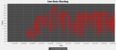
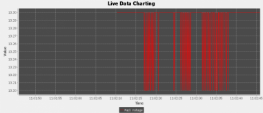
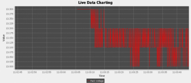
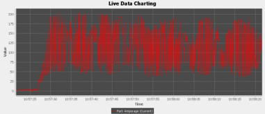
I don't have a scope with me, so the best I can do is live data from the Orion BMS. The sample rate is every 200-100ms, but you can get an idea. I am sure if I had scope with me there would be a consistent waveform.

These first two are with a pure resistive load of ~200w. My solar array was connected so you see a bit of variance in the average current. Voltage ripple is about 100mV.


Heater.pngHeater-Voltage.png


Here is my induction cooktop. It uses some high frequency stuff, so its a bit more varied.Cooktop-Voltage.pngCooktop.png
 
Top and bottom images take on quite a few values.

The middle two have only 2 and 4 values, like LSB/resolution limit. Don't consider those variations as meaningful, although can be averaged over time for slower moving higher resolution. Both show 0.1V resolution, pretty coarse.

Would want >> 120 Hz sampling to see what's happening during a sine wave. Possibly this hash is due to undersampling. Top and bottom pictures are the current reading. Since this is supposed to be nominally DC from the battery, even if it is undersampled (and not consistent timing) of sine wave that would be a huge current variation, 4:1. Could also just be noise (interference).

Really want sampling with a scope well above switching frequency to see both that and the 60 Hz.

I don't like the idea of 4:1 variation of current from battery, which indicates filtering by bulk caps doesn't really happen.
If real, affects wire loss and fuse size calculation.
 
Yeah, I agree there is some noise there, and that its not a high enough sample rate to have a lot of value.. For reference the resistive load is 200W, the induction cooktop should be around 1,800W

For that 1,800W induction cooktop load, the average current should be around 135-140A, which is roughly what I am seeing on that graph.
 
I'm 100% positive it's skin effect from AC ripple induced by the inverter because I have very high quality crimps and clean connections and terminals and it ONLY happened on the exact 2 runs of long wire out of the 30 connection I had.

Read Orion's explanation here and here (page 43).
 
I'm 100% positive it's skin effect from AC ripple induced by the inverter because I have very high quality crimps and clean connections and terminals and it ONLY happened on the exact 2 runs of long wire out of the 30 connection I had.

Read Orion's explanation here and here (page 43).

Let me also add then when I replaced those same long runs with long (2 feet) bus bar runs, the effect went away.
 
I would need to break out my AC power textbook, but that may be a good reason to use solid instead of stranded cable for bus bars.


It would be very interesting to see which inverter designs produced the smallest AC components on the battery.
 
I'm 100% positive it's skin effect from AC ripple induced by the inverter because I have very high quality crimps and clean connections and terminals and it ONLY happened on the exact 2 runs of long wire out of the 30 connection I had.

Read Orion's explanation here and here (page 43).

Seems to me there should be a pi filter between battery/BMS and inverter to attenuate switching frequencies.
FCC limits only go down to 150 kHz, but for some industrial equipment we need to suppress lower for our own and neighboring equipment benefit.

Common mode would have been easy to filter with a choke, but this is differential.

That flat busbar might have slightly lower AC impedance than the round cable, but hard to believe significant.

I don't have the source material handy but at these bus bar sizes, the skin effect is 0.
 
That flat busbar might have slightly lower AC impedance than the round cable, but hard to believe significant.
If memory serves, isn't that pretty frequency dependent though? I recall it being the square of the frequency?
 
If someone can break out a scope and get me frequency and voltage measurements, I might be able to cobble something together.

Please don't give me an excuse to buy a scope that I keep wanting but don't really need :ROFLMAO:
 
Can I buy you beer to do so? :)

And I should put one of my AC clamp probes on the cable between my batteries and inverters.
If I don't see what you do, I'll blame it on your LiFePO4 or inverter model, compared to my AGM and Sunny Island.
 
Back
Top