diy solar

diy solar

Class T Fuse VS BMS Cost / Safety

byteharmony

Sunny side up please.
Joined
Jul 29, 2022
Messages
233
Location
Milwaukee
Looking at putting together a multiple battery system today and was planning on following the advice of using a Class T fuse to protect the different batteries in parallel from each other.

The market seems to be offering those fuses form 100 Amps to 300 Amps. $20 - $100

I'm considering 2 different BMS units, a 100 AMP $80 and a 40 AMP $40.

The cells connected can easily push 150 amps.

My load could easily be limited to 30 AMPS.

If I go 100 AMP BMS $80+ 100 AMP fuse $50 = $150
If I go 40 AMP BMS $40 and that's it, the BMS may fry, it should not, it should stop an over draw, and then I'm only out $40 (and a rewire :).

Wondering if anyone has any experience with choosing the $40 40 AMP jkbms and depending on it to cut the current if it spikes?

I get that it could fry your inverter, but the inverter is limiting draw to 60 AMPS and the other battery is limited to 100 AMPS with DC breakers (Trophy).

In case you're wondering the goal, it's to extend the capacity of a single 100 Ah trophy 48v battery with multiple smaller batteries.
 
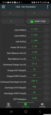
In the screenshot below of the JKBMS android app software it shows a few current protection settings.

If I just have 2 JKBMS protected batteries and one battery has a cell short out. The voltage of that battery drops like a rock. The other batteries in parallel rush current into that battery.

The BMS of the failed cell battery should shutdown with a low voltage error.
The BMS of the failed cell should shutdown with a charging current error (30 seconds is configured in my screenshot)

The BMS of the working battery should shutdown with an overcurrent protection.

How much of these BMS device features should I consider worthless?
 

Attachments

  • 384429280_1911629009275758_42413365890912823_n.jpg
    384429280_1911629009275758_42413365890912823_n.jpg
    166.2 KB · Views: 3
Why not at least put a cheap fuse in? You can get them for much less than a class-t fuse. Or a breaker?

As a question to the group, are there well documented reasons to not use breakers or cheaper fuses? I've seen mention of potentially higher resistance in the breakers, and higher failure rate in cheaper fuses, but is going all the way to class-t really necessary? There must be different levels of quality in the cheaper alternatives.
I only use breakers.
Unless a fuse is much cheaper than the breaker. (Very high current)
 
I like high AIC breakers, like some of the non-polarized midnite solar breakers.
 
@cs1234 & @timselectric thanks for your input, now things are coming together in my head!!

Looking at the Midnight solar products and a lower cost fuse I'm seeing solutions for 30 - 60 amps (10 and 6 awg wire) that are making more cents $ ;).

One more follow up: @cs1234 why the non-polarized breakers?
- Non -polarized are cheaper, same AIC and have a face based mount ($21.58)
- Polarized are more expensive, same AIC and have a DIN rale mount ($25)


Also noticing Midnight talking about NEC2008 and having a breaker for the charge controller and ground. I would guess most people are not aware of this requirement. I was not. (see attached PDF).

I believe my sol ark breakers for the battery connections take care of this requirement for me.

APC ups devices with SLA batteries use cheaper, not class T fuses. Are their any Class T fuse guys out there who would like to introduce flaws to the thoughts we're sharing?
 

Attachments

  • MNDC-GFP_Manual_V2.pdf
    436.8 KB · Views: 3
Class T fuses have higher AIC ratings. Blow super fast. And open a larger gap, to not sustain an arc, better.
You don't always need the best. But, you can't go wrong choosing it.
 
Also noticing Midnight talking about NEC2008 and having a breaker for the charge controller and ground. I would guess most people are not aware of this requirement. I was not. (see attached PDF).

Many of us are using a breaker on both sides of the solar charge controller. I use a dual pole breaker between the PV and the solar charge controller. It's rated for what the PV can produce, but it's mostly used as a way to shut off PV power to the solar charge controller.

Keep in mind that a 100 amp BMS is (usually) a continuous rating. The BMS can sustain a higher amperage output for a short period of time.

Thanks @HRTKD, I think you make a good point about a BMS providing more than it's rated capacity and cleared up why a dual pole breaker is used in the attached diagram for the Midnight Solar breakers. The same principle you described also applies to a ground surge in current, it would trip the PV power coming in.

Coming back to a topic @cs1234 raised with breaker polarity:
It looks like the plus on the breaker goes to the power source positive, in other words battery positive, not charge controller positive.

Likewise for solar, the plus goes to the positive of the solar panel, not the plus on the charge controller.

Is that right?
 

Attachments

  • MNDC-GFP_Manual_V2.pdf
    436.8 KB · Views: 4
One more follow up: @cs1234 why the non-polarized breakers?
- Non -polarized are cheaper, same AIC and have a face based mount ($21.58)
- Polarized are more expensive, same AIC and have a DIN rale mount ($25)

I run multiple batteries in parallel. I prefer the non-polarized breakers because I could have massive (relatively) amounts of current coming in the opposite direction as well.

A polarized breaker is designed to best stop overflow in one direction, i.e. a battery sending power out to the inverter. But with paralleled batteries, if one of them bit the dust, it could be sending large amounts of current into my remaining batteries.. so the opposite direction of the polarized breaker.

Whether it will really make a difference in practice or not, I don't know. I would have to try shorting out batteries to find out. ?
 
Back
Top