diy solar

diy solar

Combining Victron with Fronius inverter

ctsit

New Member
Joined
Mar 31, 2022
Messages
33
Hi all,
Recently my NET METERING system went online. It comprises of the following equipment:
1. Fronius 5KW GEN24Plus
2. Fronius Meter
3. 12 Sharp 410w giving a total 4920kwp
4. BYD HVM 11.04kwh
Currently there is no back up mode which means that is the grid goes down the only power available will be through the PV Point (max 16amp) which is not connected. I Intent to introduce the back up switch board provided by Fronius at a later stage.
During winter (I live in Athens, Greece) I see daily productions ranging from 15kwh on a cloudy day to 23.7 kwh on a sunny day.
Instead of either buying more battery or/and the Fronius back up functionality I was think to introduce a Victron inverter with a set of 15kwh of 48v batteries and an additional 3000kwp of solar.

The logic is that I utilize all the power produced by the Net metering system and that in General all power to the house will come from Victron. The grid (and therefore Fronius) will be directly connected to the AC In of the Victron (and maybe the PV Point of the Fronius also which will mean that a Quattro will be needed) .
Depending on the SOC of the batteries of the Victron (and other parameters) the power demand will be shared with the Fronius.
Batteries of the Victron will be charged in combination to the SmartSolar charger and Quattro that will get power from Fronius.
As nice to haves are some automations not to charge the batteries from Fronius if e.g. there is no sunshine but this is less important. The max power coming from Fronius will be 20amps during the morning and 5amps during the night unless the SOC of the Victron batteries is at 20% then it will passthrough all demand to the Fronius.
Goes without saying that all works will be performed by a certified electrician providing all necessary certifications and paperwork.
Is the above description doable? Are there flaws that might create issues? I want to know before I start asking for quotes.
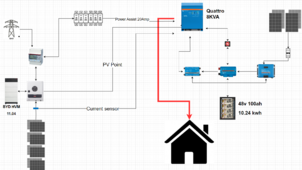
I am attaching a schema of the logic (there may be design flows)
1709046200086.png
 
Last edited:
I'm not confident I'm following you, but I feel it may be prudent to point out that while the Quattro has two AC inputs, only ONE may be active at any time. Given that grid and PV inverter power must be in sync, I don't think it's prudent to have two separate inputs.

Something to consider, Victron ESS enables extremely flexible grid interaction. Many use it to optimize when to use cheap grid power and when to sell surplus based on TOD/rates. Having the Fronius AC coupled to the Victron means the PV inverter can also charge batteries.
 
Hi all,
Recently my NET METERING system went online. It comprises of the following equipment:
1. Fronius 5KW GEN24Plus
2. Fronius Meter
3. 12 Sharp 410w giving a total 4920kwp
4. BYD HVM 11.04kwh
Currently there is no back up mode which means that is the grid goes down the only power available will be through the PV Point (max 16amp) which is not connected. I Intent to introduce the back up switch board provided by Fronius at a later stage.
During winter (I live in Athens, Greece) I see daily productions ranging from 15kwh on a cloudy day to 23.7 kwh on a sunny day.
Instead of either buying more battery or/and the Fronius back up functionality I was think to introduce a Victron inverter with a set of 15kwh of 48v batteries and an additional 3000kwp of solar.

The logic is that I utilize all the power produced by the Net metering system and that in General all power to the house will come from Victron. The grid (and therefore Fronius) will be directly connected to the AC In of the Victron (and maybe the PV Point of the Fronius also which will mean that a Quattro will be needed) .
Depending on the SOC of the batteries of the Victron (and other parameters) the power demand will be shared with the Fronius.
Batteries of the Victron will be charged in combination to the SmartSolar charger and Quattro that will get power from Fronius.
As nice to haves are some automations not to charge the batteries from Fronius if e.g. there is no sunshine but this is less important. The max power coming from Fronius will be 20amps during the morning and 5amps during the night unless the SOC of the Victron batteries is at 20% then it will passthrough all demand to the Fronius.
Goes without saying that all works will be performed by a certified electrician providing all necessary certifications and paperwork.
Is the above description doable? Are there flaws that might create issues? I want to know before I start asking for quotes.
I am attaching a schema of the logic (there may be design flows)
View attachment 198754
I was looking at this myself and ran across this page. https://community.victronenergy.com/questions/188747/why-combining-fronious-with-victron.html Reading that thread, there are times a Fronius may cause light flicker so be aware of that aspect. With your proposed additional PV, you will be close to the Factor 1.0 Rule so keep that in mind. https://www.victronenergy.com/live/ac_coupling:start
 
I'm not confident I'm following you, but I feel it may be prudent to point out that while the Quattro has two AC inputs, only ONE may be active at any time. Given that grid and PV inverter power must be in sync, I don't think it's prudent to have two separate inputs.

Something to consider, Victron ESS enables extremely flexible grid interaction. Many use it to optimize when to use cheap grid power and when to sell surplus based on TOD/rates. Having the Fronius AC coupled to the Victron means the PV inverter can also charge batteries.
To provide some clarity. The cable providing power to my house will be connected to the AC Out of the Quattro. In the ACIn1 I will connect a cable connected to the panel that the fronius and grid power are connected. There will be no Back feed from Victron and Fronius will continue to regulate everything.
In the ACIn2 of the Quattro I will connect the PV out of the Fronius. This PV out is powered only when there is a grid outage. Therefore always only one ACIn will be active.
Regarding the power synchronization I don't understand, the whole point of the Quattro is to work as a UPS for the entire house.
What I am basically trying to describe is that the house will always get powered either from Victron or through Victron relay switch. But never directly from Fronius.
Does this sound possible or it might create problems.
 
I was looking at this myself and ran across this page. https://community.victronenergy.com/questions/188747/why-combining-fronious-with-victron.html Reading that thread, there are times a Fronius may cause light flicker so be aware of that aspect. With your proposed additional PV, you will be close to the Factor 1.0 Rule so keep that in mind. https://www.victronenergy.com/live/ac_coupling:start
Thanks, of course in my case the Fronius takes care of the back feed for the NEt MEtering and also charges the BYD battery.
But I want to emphasize on another question that I didn't rase in my original post.
Can I synchronize the charging from e.g. a Quattro and smartsolar?
The quattro will charge the batteries from power receiving from Fronius and it will appear as load for the fronius and the smartsolar from the PV connected. But is this possible AC -> DC charging (Quattro) and DC charging (Smartsolar) at the same time ? If I use a Cerbo GX can those two be in synch?
I have the same question in another thread as I would possibly consider a hybrid DC coupled and AC coupled system.

I will have 2 PV arrays and will have the ability to divert one that is setup for DC SCC's when the batteries on another system hit full charge. My plan is to have switching in place to allow the PV power to be diverted.
I wanted to have a switch but you will need to be very careful when changing destinations.
1. You have to disconnect the PV
2. Change the flow of energy to your other system.
3. Reconnect the PV and again all of this if done on full sunshine may affect the lifecycle of your products.

Alternatively I would propose to use something like home assistant and shelly circuit breakers (or any other similar logic products) so that if battery1 if fully charged then the Shelly circuit breaker will open and the original inverter will see the charging of Battery2 as another load.
You can also set rules like amount of PV production etc. and what is most important is that you can track the energy going through the shelly circuit breaker.
Just a disclaimer, I am very new to all of these so I am describing what I have read, I will buy one of these products and try out if they work as advertised.
 
I'm not confident I'm following you, but I feel it may be prudent to point out that while the Quattro has two AC inputs, only ONE may be active at any time. Given that grid and PV inverter power must be in sync, I don't think it's prudent to have two separate inputs.

Something to consider, Victron ESS enables extremely flexible grid interaction. Many use it to optimize when to use cheap grid power and when to sell surplus based on TOD/rates. Having the Fronius AC coupled to the Victron means the PV inverter can also charge batteries.
I have an off grid system (fully operational using string inverters) with a Multiplus, so AFAIK, unless the microinverter has a stand-alone mode it won't work connected to the MP AC in. (I've tried it with a cheap micro inverter, and my searches in the Victron haven't revealed a work-around).

Edit for clarification: Note that I understand that the micro inverter can just be plugged into the AC out side of the multiplus but you have to install a separate meter to determine how much power you're getting from the array and take other steps to integrate it into the rest of the Victron system

If the microinverter could connect through the AC input, the multiplus would keep track of it without more equipment and integration.
I am just exploring how and if micro-inverter driven panels could be integrated.


Have you ever come across a device that would provide a low-power reference AC to the micro inverter so that it would produce stand-alone AC.
Is this even a good idea?
 
Last edited:
I have an off grid system with a Multiplus, so AFAIK, unless the microinverter has a stand-alone mode it won't work connected to the MP AC in. (I've tried it with a cheap micro inverter, and my searches in the Victron haven't revealed a work-around)

Have you ever come across a device that would provide a low-power reference AC to the micro inverter so that it would produce stand-alone AC.
Is this even a good idea?
He can connect the victron in parallel. You won't have pv in a power outage but it would otherwise work as normal- victron sees export from fronius and charges batteries. Victron sees loads via CT it discharges the battery to support the loads.

also the victron is designed to work very well with Fronius inverters- he wont have any issues
 
Last edited:
I have an off grid system with a Multiplus, so AFAIK, unless the microinverter has a stand-alone mode it won't work connected to the MP AC in. (I've tried it with a cheap micro inverter, and my searches in the Victron haven't revealed a work-around)

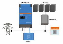
AC coupled should be on the MP AC output like this and not the AC input.


1709154246925.png
Have you ever come across a device that would provide a low-power reference AC to the micro inverter so that it would produce stand-alone AC.
Is this even a good idea?

If you wire this with grid tie inverter on the MP output, with grid down the MP will provide AC power from the batteries and the PV inverter will continue to operate.
 
I am not sure I understand the problem, so apologies if the question sounds stupid.
Right now I have a small victron multiplus 800va connected to an outlet of the house to work as UPS.
As I said the house is connected to the Grid and to a Fronius inverter.
The Multiplus 800va has a battery and powers some equipment (so has a load).
The same general principal I think applies with the Quattro.
Between the house power in and the grip/fronius I will place the quattro. The only way power reaches the house will be through the quattro, why would it be a problem?
The power originates initially from Fronius and if the BYD batteries SOC reaches 20% fronius transfers the power request to the grid.
Why would there be power synchronisation issues. The Quattro will not feedback power but act as a UPS for the entire house. Of course I want to utilize also the power assist feature which means the if needed the Quattro will combine its power with that of the fronius.
Again apologies for my ignorance
 
Last edited:
AC coupled should be on the MP AC output like this and not the AC input.


View attachment 199027


If you wire this with grid tie inverter on the MP output, with grid down the MP will provide AC power from the batteries and the PV inverter will continue to operate.
If the PV inverter, which in my case has also a battery, is connected along with the grid on ACIn1 of the quattro and the Fronius PV point is connected in the ACIn2 wouldn't I achieve the same result of having power in a blackout?
Stating the obvious, the Fronius PV point provides power, either through solar or battery, when the grid power is down. The big downside is the limited performance which in this case the output is reduced to about 3600w.
I don't know for certain how your Fronius works in grid down but grid tie inverters will shut down when grid power is lost. If the Quattro is after the Fronius AC connection, the Fronius will shut down when grid power is lost.

When wired according to the Victron diagram in my previous post you quoted, the inverter supplies AC power when grid power is down and the grid tie inverter will not detect a grid down situation and will not shut down. The Quattro will control export to grid power both when grid power is available or when grid is down by not allowing export.

You don't want the grid tie inverter feeding in before the Quattro but after it. With a grid down situation and power coming from grid tie PV to the Quattro AC output, any loads will be powered by the grid tie power coming in, any excess will be used by the Quattro to charge batteries. If PV can not supply enough power, the Quattro will supply power by drawing from the batteries.
 
If the PV inverter, which in my case has also a battery, is connected along with the grid on ACIn1 of the quattro and the Fronius PV point is connected in the ACIn2 wouldn't I achieve the same result of having power in a blackout?

Sunshine Eggo explained this well enough here. https://diysolarforum.com/threads/combining-victron-with-fronius-inverter.79722/post-1021503 The 2 outputs of the Quattro are for when grid power is down and just powering critical loads is desired such as a refrigerator or freezer. These critical items are on one AC output. The non critical loads are powered by the other AC output and those loads will not be powered in a grid down scenario.

Stating the obvious, the Fronius PV point provides power, either through solar or battery, when the grid power is down. The big downside is the limited performance which in this case the output is reduced to about 3600w.
 
Sunshine Eggo explained this well enough here. https://diysolarforum.com/threads/combining-victron-with-fronius-inverter.79722/post-1021503 The 2 outputs of the Quattro are for when grid power is down and just powering critical loads is desired such as a refrigerator or freezer. These critical items are on one AC output. The non critical loads are powered by the other AC output and those loads will not be powered in a grid down scenario.
can I have all my loads in the AC Output for critical loads, meaning treating the entire electrical panel as a critical load?
This will mean that everything will be treated as critical. Of course I understand that there are limitations depending on the type of load, but if I have a 10000va Quattro that gives out 8kw of power that is more than plenty for what I have in the house.
 
AC coupled should be on the MP AC output like this and not the AC input.


View attachment 199027


If you wire this with grid tie inverter on the MP output, with grid down the MP will provide AC power from the batteries and the PV inverter will continue to operate.
Yes - and you have to install a separate meter to determine how much power you're getting from the array.

If it could run through the AC input, the multiplus would keep track of it.
My apologies, I should have made my exact situation and needs clear.
 
Last edited:
AC coupled should be on the MP AC output like this and not the AC input.


If you wire this with grid tie inverter on the MP output, with grid down the MP will provide AC power from the batteries and the PV inverter will continue to operate.

I edited the original post to make it clear what type of answer I am actually looking for. I've already successfully put the microinverter on the AC out side.
 
Last edited:
AC coupled should be on the MP AC output like this and not the AC input.


View attachment 199027


If you wire this with grid tie inverter on the MP output, with grid down the MP will provide AC power from the batteries and the PV inverter will continue to operate.
I edited the original post to make it clear what type of answer I am actually looking for. I've already successfully put the microinverter on the AC out side.
 
Last edited:
Back
Top